background image

22  |  SAMLEX AMERICA INC.    


APPENDIX A

SECtION 4  |  

Parameter Setup

•   

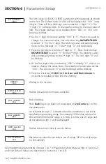
AC input is available and eVo

TM

 inverter/Charger is operating in Charging Mode:


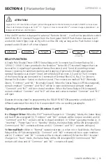
When the battery voltage rises to the set upper threshold of “BATT OVER VOLT”, the Transfer 
Relay will be de-energized, charging and pass through will be stopped and PWM drive to the 
Inverter Section will be switched OFF. Fault message “Battery over voltage!” will be displayed 
on the LCD screen. The Green LED marked “Status” will switch OFF and the Red LED marked 
“Fault” will remain ON steady. The Buzzer on EVO

TM

 Inverter/Charger will beep steady. The fault 

will be cleared automatically when the battery voltage drops to 0.5V below to the set upper 
threshold of “BATT OVER VOLT”. The unit will start in Inverting Mode, synchronize with the AC 
input and then, the Transfer Relay will be energized to transfer to AC input at zero crossing. 
The unit will, thus, resume operation in “Charging Mode”.  

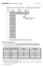
SELECT GROUP

CHARGE CURVE

BULK CURRENT

40 A

BATT OVER VOLT

16.00 V

Enter Key

ò

Up Key x 5

ò

BATT OVER VOLT

16.00 V

ò

KEY IN PASSWORD

0000

Enter Key

ò

Password 8052

See Section 4.3.1

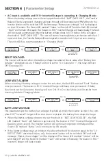
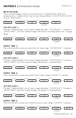
ReSet VoLtAGe:

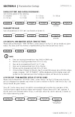
The inverter will restart when the battery voltage rises above this set value after "Battery low 
voltage!" shutdown occurs. If Relay Function is set for "3 = Generator 1", the relay will turn 
OFF (See page 35).

SELECT GROUP

CHARGE CURVE

BULK CURRENT

40 A

RESET VOLTAGE

14.0 V

Enter Key

ò

Up Key x 6

ò

RESET VOLTAGE

14.0 V

ò

KEY IN PASSWORD

0000

Enter Key

ò

Password 8052

See Section 4.3.1

LoW VoLt ALARM:

When inverting, if battery voltage is under the set value, the Red LED marked "Fault" flashes 
once per second. The buzzer in EVO

TM

 Inverter/Charger will beep once per second. If Relay 

Function is set for Generator, the relay will turn ON. If in On-Line Mode, it will transfer from 
Inverting Mode to Charging Mode.

SELECT GROUP

CHARGE CURVE

BULK CURRENT

40 A

LOW VOLT ALARM

11.00 V

Enter Key

ò

Up Key x 7

ò

LOW VOLT ALARM

11.00 V

ò

KEY IN PASSWORD

0000

Enter Key

ò

Password 8052

See Section 4.3.1

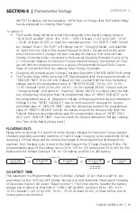
BAtt LoW VoLtAGe:

This parameter sets the battery low voltage threshold at which the Inverter Section / the com-
plete EVO

TM

 Inverter/Charger will be shut down to protect the battery from deep discharge: 

•   When the battery voltage drops to the set threshold of “BATT LOW VOLTAGE”, the Red 

LED marked “Fault” will flash once per second. The buzzer in EVO

TM

 Inverter/Charger will 

beep once per second. The Inverter Section will continue to operate normally and the 
Green LED marked “Status” will continue to be ON steady.

•   If the battery voltage stays at or below the above threshold for duration equal to the “LV 

DETECT TIME” described below, only the Inverter Section will be switched OFF and fault  
message “Battery low voltage!” will be displayed. The Green LED marked “Status” will be 
switched OFF and the Red LED marked “Fault” will remain ON steady. The buzzer in EVO

TM


Inverter/Charger will beep steady.

Summary of Contents for EVO-2212E

Page 1: ...EvolutionTM Series Inverter Charger Pure Sine Wave Models EVO 2212E EVO 3012E EVO 2224E EVO 4024E For use with 230 VAC Models Please read this manual before operating Firmware Rev 0 70 Owner s Manual ...

Page 2: ...FFICIENCY OR SUITABILITY OF ANY TECHNICAL OR OTHER INFORMATION PROVIDED IN ITS MANUALS OR OTHER DOCUMENTATION 2 ASSUMES NO RESPONSIBILITY OR LIABILITY FOR LOSSES DAMAGES COSTS OR EXPENSES WHETHER SPECIAL DIRECT INDI RECT CONSEQUENTIAL OR INCIDENTAL WHICH MIGHT ARISE OUT OF THE USE OF SUCH INFORMATION THE USE OF ANY SUCH INFORMATION WILL BE ENTIRELY AT THE USERS RISK Samlex America reserves the rig...

Page 3: ...utilisateur ne suit pas les instruc tions i INFO Indicates useful supplemental information Please read these instructions before installing or operating the unit to prevent per sonal injury or damage to the unit WARNING 1 DANGER To reduce risk of explosion do not install in machinery space or in area in which ignition protected equipment is required to be used 2 CAUTIONS a To prevent damage due to...

Page 4: ...ds 12 WARNING To reduce risk of electric shock and fire Installation should be carried out by certified installer and as per Local and National Electrical Codes Do not connect to circuit operating at more than 280 Volts to Ground Both AC and DC voltage sources are terminated inside this equipment Each circuit must be individually disconnected before servicing Do not remove cover No user serviceabl...

Page 5: ...eurs pour les circuits d entrée CA et le tableau 3 3 pour le dimensionnement des disjonc teurs pour les circuits de sortie AC Codes électriques nationaux et locaux remplaceront ces lignes directrices 8 Les bornes de la batterie sont conçus pour se connecter sur le terrain avec des conducteurs en cuivre qui sont dimensionnés en fonction de 90 C Voir le tableaux 3 1 pour les tailles recommandées pou...

Page 6: ...spect to time For example a pure sine wave that alternates between peak values of Positive 169 68V and Negative 169 68V has an RMS value of 120 VAC Also for a pure sine wave the RMS value Peak value 1 414 Voltage V Volts It is denoted by V and the unit is Volts It is the electrical force that drives electrical current I when connected to a load It can be DC Direct Current flow in one direction onl...

Page 7: ...s of the load It is not consumed by the inductive and capacitive elements in the load but a certain value travels from the AC source to these elements in the half cycle of the sinusoidal voltage Positive value and the same value is returned back to the AC source in the half cycle of the sinusoidal voltage Negative value Hence when averaged over a span of one cycle the net value of this power is 0 ...

Page 8: ...ximum Continuous Running AC Power AC to DC Switched Mode Power Supplies SMPS This type of power supply is used as stand alone power supply or as front end in all electronic devices powered from Utility Grid e g in audio video computing devices and battery chargers Please see Section 4 for more details on SMPS When this power supply is switched ON its internal input side capacitors start charging r...

Page 9: ...rosses zero V instantaneously Modified Sine Wave VRMS 230V Vpeak 250 to 320V Sine Wave VRMS 230VAC Vpeak 325 22V 20 ms VOLTS VOLTS Vpeak 325 22V Vpeak 250 to 320V VRMS 230 VAC Fig 1 1 Pure and Modified Sine Waveforms for 230VAC 50 Hz The 230VAC output waveform of the EvolutionTM series inverters is a Pure Sine Wave like the waveform of Utility Grid power Please see Sine Waveform represented in the...

Page 10: ...d glitches in monitors Some examples of devices that may not work properly with Modified Sine Wave and may also get damaged are given below Laser printers photocopiers and magneto optical hard drives Built in clocks in devices such as clock radios alarm clocks coffee makers bread makers VCR microwave ovens etc may not keep time correctly Output voltage control devices like dimmers ceiling fan moto...

Page 11: ...rter Multiply the Maximum Continuous Running Power Rating Active Power Rating in Watts of the appliance device by recommended Sizing Factor to arrive at the Maximum Continuous Running Power Rating of the inverter TABLE 1 6 INVERTER SIZING FACTOR Type of Device or Appliance Inverter Sizing Factor See Note 1 Air Conditioner Refrigerator Freezer Compressor based 5 Air Compressor 4 Sump Pump Well Pump...

Page 12: ...ely used to convert the incoming AC power into various voltages like 3 3V 5V 12V 24V etc that are used to power various devices and circuits used in electronic equipment like battery chargers computers audio and video devices radios etc These power supplies use large capacitors in their input section for filtration When the power supply is first turned on there is a very large inrush current drawn...

Page 13: ... an inverter that has Maximum Continuous Power Rating of 200 Watts Input voltage Peak Inrush Current Inrush current Rated Steady State Input RMS Current NOTE Voltage and Current scales are different Fig 1 2 Inrush current in an SMPS TIME Peak Current RMS Current Non linear Input Current Input Sine Wave Voltage CREST FACTOR PEAK CURRENT 3 RMS CURRENT NOTE Voltage and Current scales are different Vo...

Page 14: ...otive battery industry rates batteries at a discharge current or C Rate of C 20 Amperes corresponding to 20 Hour discharge period The rated capacity C in Ah in this case will be the number of Amperes of current the battery can deliver for 20 Hours at 80ºF 26 7ºC till the voltage drops to 1 75V Cell i e 10 5V for 12V battery or 21V for 24V battery For example a 100 Ah battery will deliver 5A for 20...

Page 15: ... Point Voltage in a shorter period of time On the other hand if the battery delivers a lower discharge current the battery will be discharged to the End Point Voltage after a longer period of time Mathematically C Rate is defined as C Rate Capacity C in Ah Discharge Time T Table 1 8 gives some examples of C Rate specifications and applications Table 1 8 Discharge current rates C Rates Hours of dis...

Page 16: ... 60 70 80 90 100 110 120 130 16 5 16 0 15 5 15 0 14 5 14 0 13 5 13 0 12 5 12 0 11 5 11 0 10 5 10 0 9 5 9 0 C 5 C 40 C 20 C 10 DISCHARGE CHARGE C 20 C 3 C 5 C 10 C 100 33 0 32 0 31 0 30 0 29 0 28 0 27 0 26 0 25 0 24 0 23 0 22 0 21 0 20 0 19 0 18 0 24V 12V Fig 1 4 Charging Discharging Curves for Typical Flooded Lead Acid Battery 1 4 7 Reduction in Usable Capacity at Higher Discharge Rates Typical in...

Page 17: ...50 Amperes 1 Hour 1 4 8 State of Charge SOC of a Battery Based on Standing Voltage The Standing Voltage of a battery under open circuit conditions no load connected to it can approximately indicate the State of Charge SOC of the battery The Standing Voltage is measured after disconnecting any charging device s and the battery load s and letting the battery stand idle for 3 to 8 hours before the vo...

Page 18: ...s inside the battery and produces a Negative Voltage Coefficient during charging discharging the terminal voltage drops with rise in temperature and rises with drop in temperature The amount of discharging current or C Rate A battery has non linear internal resistance and hence as the discharge current increases the battery terminal voltage decreases non linearly The discharge curves in Fig 1 4 sh...

Page 19: ...Charge 85 State of Discharge 15 State of Charge at very high C rate discharge current of C 3 Amps 100 State of Discharge 0 State of Charge at high C Rate discharge current of C 5 Amps 100 discharged 0 State of charge at lower C rate Discharge current of C 10 Amps It is seen that at DC input voltage of 10V 20V the battery is completely discharged for C rate discharge current of C 5 and lower In vie...

Page 20: ...te the AC watts The next step is to estimate the DC current in Amperes A from the AC watts as per Formula 2 above An example of this calculation for a 12V inverter is given below Let us say that the total AC Watts delivered by the inverter 1000W Then using Formula 2 above the approximate DC current to be delivered by the 12V batteries 1000W 10 100 Amperes or by 24V batteries 1000W 20 50A Next the ...

Page 21: ...es may be charged at 10 to 20 of their Ah capacity Ah capacity based on 20 Hr Discharge Rate Also for complete charging return of 100 capacity it is recommended that 4 Stage Charger may be used as follows Normal Charging 3 Stages Stage 1 Bulk Stage at constant current Stage 2 Absorption Stage at constant voltage Stage 3 Float Stage at constant voltage Equalization Charging 4 Stages Stage 1 Bulk St...

Page 22: ...ans Additional air inlet vents at the bottom not shown 9A 9B RJ 45 Jacks for Communication Ports COMM 1 and COMM 2 For RS 485 networking and MODBUS Serial Communication Protocol for future use 9C 9D RJ 45 Jacks for Communication Ports COM 3 and COM 4 For CANbus Serial Communication Protocol for future use 10A to 10C Knock outs for AC wiring inlet exit wiring entry Diameter 27 8mm 1 3 32 For condui...

Page 23: ...ne 8 Generator Input Ground 9 Generator Input Neutral 10 AC Output Line 11 AC Output Ground 12 AC Output Neutral 13 Male Female Insulated Quick Disconnect for disabling Output Neutral to Chassis Ground bond in Inverter Mode Please see Sections 4 5 1 to 4 5 3 and Fig 3 12 Fig 2 2 Layout Back 1 1 13 3 2 Behind Cover Plate 2 9 10 11 4 8 7 6 5 12 O U TPU T N EU TRA L O U TPU T G N D O U TPU T LIN E G ...

Page 24: ...Red LED Fault 5 Navigation Key Back 6 Navigation Key Up 7 Navigation Key Down 8 Navigation Key Enter 9 SD Card Slot FAT16 32 format Up to 16GB 10 RJ 45 Jack At the back not shown 11 RJ 45 Data Cable Straight Wired 10 meter 33 feet length Fig 2 4 b 2 4 REMOTE CONTROL EVO RC FIG 2 4 OPTIONAL Fig 2 4 a Optional Remote Control evo rc Fig 2 4 b Cable for Remote Control ...

Page 25: ...G 16 2 5 mm2 AWG 14 4 mm2 AWG 12 6 mm2 AWG 10 EVO 2212E 3 6 EVO 2224E 3 6 EVO 3012E 3 6 EVO 4024E 3 6 Owner s Manual Quick Start Guide 2 5 BATTERY TEMPERATURE SENSOR EVO BCTS FIG 2 5 a Fig 2 5 a Temperature Sensor Model EVO BCTS Fig 2 5 b Temperature Sensor Installation 1 Temperature Sensor Mounting hole 10mm 0 39 suitable for 3 8 or 5 16 battery studs 2 RJ 45 Plug 3 5 meter 16 5 ft cable Note Mou...

Page 26: ...lbs Use 4 pcs of 1 4 or M6 mounting bolts and lock washers Installation on marine craft and vessels will require use of Drip Shield on top of the unit to protect against ingress of water dripping from top Drawing of Drip Shield is given at Fig 3 1 a Configurations using the Drip Shield are shown under Mounting Orientation Cooling The unit has openings on the front bottom and back for cooling and v...

Page 27: ...rminals facing left Please see Fig 3 3 Fig 3 3 Mounting Arrangement 1 On Vertical Surface CAUTION Ensure there is OVER 200 mm clear space surrounding the inverter for ventilation ATTENTION Assurer qu il y a PLUS QUE 200 mm d espace DÉGAGÉ entourant l onduleur pour faciliter la ventilation Section 3 Installation a Non Marine Installation b Marine Installation 10 mm Gap Top surface of Drip Shield 55...

Page 28: ... Fig 3 5 Series Connection When two or more batteries are connected in series their voltages add up but their Ah capacity remains the same Fig 3 5 shows 4 pieces of 6V 200 Ah batteries connected in series to form a battery bank of 24V with a capacity of 200 Ah The Positive terminal of battery 4 becomes the Positive terminal of the 24V bank The Negative terminal of battery 4 is connected to the Pos...

Page 29: ... connection becomes the Negative terminal of the 12V battery bank 3 4 3 Series Parallel Connection Fig 3 7 Series Parallel Connection Figure 3 7 shows a series parallel connection consisting of four 6V 200 Ah batteries to form a 12V 400 Ah battery bank Two 6V 200 Ah batteries Batteries 1 and 2 are connected in series to form a 12V 200 Ah battery String 1 Similarly two 6V 200 Ah batteries Batteries...

Page 30: ... at the same charging discharging current and thus will be charged discharged to the same state at the same time None of the batteries will see an overcharge overdischarge condition If the Positive output cable of the inverter charger Cable A is connected to the Positive battery post of the first battery Battery 1 in Fig 3 6 or to the Positive battery post of the first battery string Battery 1 of ...

Page 31: ...même courant ainsi elles seront rechargées à l état pareille au même temps Aucune des batteries auront une condition de surcharge Si le câble positif de sortie du chargeur de batterie Câble A est lié à la borne positive de la première batterie La batterie 1 dans la Fig 3 6 ou à la borne positive de batterie qui est liée au premier fil Le fil 1 et La Batterie 1 Fig 3 7 et puis le câble négatif de s...

Page 32: ...r EVO BCTS The following DC side connections are required to be made see Fig 3 8 Deep cycle batteries are connected to the battery input terminals 1 and 2 The terminals are provided with protective covers RED for Positive and BLACK for Negative Fit these covers once connections have been made For details on sizing and charging of batteries please refer to Section 1 4 under General Information Lead...

Page 33: ... heavy current that will produce sparking on the last contact in the input loop even when the unit is in powered down condition Ensure that the fuse is inserted only after all the connections in the loop have been completed so that sparking is limited to the fuse area Flow of electric current in a conductor is opposed by the resistance of the conductor The resistance of the conductor is directly p...

Page 34: ... négative de l appareil Si les polarité de l entrée sont mise à l envers le fusible CC externe du côté d entrée va s exploser et peut causer des dégâts permanent à l onduleur ATTENTION La section d entrée de l onduleur a des condensateurs de grande valeur qui sont connecté aux bornes d entrées Tant que le boucle de connexion d entrée CC la borne de la batterie le fusible la borne d entrée positive...

Page 35: ...harge de puissance Si la tension baisse trop ils pourraient pas marcher et même seront endommager Circuit de rechargement de batterie La perte de tension pourrais causer une perte de puissance disproportionée Par exemple une perte de tension à 5 peut réduire le courant de charge par une pourcentage beaucoup plus grande que 5 3 5 4 Fuse Protection In The Battery Circuit A battery is an unlimited so...

Page 36: ...y is connected to terminals 1 2 shown in Fig 3 8 The terminal consists of M10 Stud Nut Tightening torque for the nut is 70 kgf cm 5 lbf ft Sizes of cables and fuses are shown in Table 3 1 Sizing is based on safety considerations specified in British Standard BS7671 See details under Notes for Table 3 1 3 5 6 DC Input Connection for External Charger External charger is connected to terminals consis...

Page 37: ... DC Input Current at Column 2 Next standard capacity is to be used 3 Columns 5 and 6 indicate cable conductor size that is based on the following 2 considerations Thicker conductor out of the following 2 considerations has been chosen a As per guidelines in British Standard BS 7671 Table 4E 1A Reference Method C for 2 cables Following have been considered i Ampacity the brecker size at Column 3 ii...

Page 38: ... size and the stud sizes on the inverter and battery ends 3 5 8 Reducing Rf Interference To reduce the effect of radiated interference shield the wires with sheathing copper foil braiding For details refer to Limiting Electro Magnetic Interference at Section 1 3 4 3 5 9 Taping Battery Wires Together To Reduce Inductance Do not keep the battery wires far apart Keep them taped together to reduce the...

Page 39: ...6 Set Screw M4 4 Grid Input Line 5 Grid Input Ground 6 Grid Input Neutral 7 Generator Input Line 8 Generator Input Ground 9 Generator Input Neutral 10 AC Output Line 11 AC Output Ground 12 AC Output Neutral 13 Male Female Insulated Quick Disconnect for disabling Ouptut Neutral to chassis Ground bond in Inverter Mode Please see Section 4 5 1 to 4 5 3 and Fig 3 1 2 1 13 3 2 Behind Cover Plate 2 9 10...

Page 40: ... le neutre de la sortie CA de l unité dans le Mode de l onduleur décharge obtient lié au châssis métallique de l unité à travers la interne Neutre à châssis relais de commutation Relais K 4 Fig 4 1 Dans Mode de chargement l interne Neutre à châssis relais de commutation déconnecte le neutre de la connexion de sortie AC du châssis de l unité Le neutre de la connexion de sortie CA de l unité va obte...

Page 41: ...limenté par une autre source de courant alternatif Une telle connexion peut entraîner un fonctionnement parallèle de différen tes sources d énergie et la puissance AC de l autre source de courant alternatif est réinjecté dans l unité qui va in stantanément endommager la section de sortie de l unité et peuvent aussi poser un risque d incendie et de sécurité Si un centre panneau de disjoncteur élect...

Page 42: ... dans le cadre du câblage d alimentation est active uniquement lorsque cette mauvaise connexion est établie lorsque l appareil est en état hors et est allumé par la suite Si la tension d entrée CA de la Grille générateur est erronée connecté nourri aux connexions de sortie CA lorsque l appareil est en état la protection ci dessus ne fonctionnera pas et la Section de l onduleur sera brûlé instantan...

Page 43: ...ocal Electrical Codes ATTENTION Breakers AC pour les circuits d entrée AC ont pas été fournis en interne Ceux ci doivent être fournies à l extérieur par l installateur utilisateur sur la base des directives données ci dessous Se il vous plaît noter que les directives ci dessous sur dimensionnement des câbles et protection contre les surintensités seront remplacées par les nationaux codes électriqu...

Page 44: ...r Input Settings GRID MAX CURRENT and GEN MAX CURRENT All the 4 models EVO 2212E 2224E 3012E and 4024E come with Input GRID MAX CURRENT and GEN MAX CURRENT set at safe default value of 16A This default value has been used for convenience of powering the units from the standard 16A mains power inlet plug on 230 VAC 50Hz motorhome caravan vehicle TABLE 3 2 1 SIZING OF GRID AND GENERATOR INPUT WIRING...

Page 45: ... programmed using the optional Remote Control EVO RC Please see page 26 at Appendix A under Section 4 5 Group 2 Parameter Setup for input setting GRID MAX CURRENT and GEN MAX CURRENT The desired value can be programmed to match the available Ampere capacity of grid feeder circuit rated Ampere capacity of the generator The default value of GRID MAX CURRENT and GEN MAX CURRENT for all 4 models has b...

Page 46: ... breaker Standard Moulded Case Circuit Breaker MCCB for 230VAC 50Hz Consumer Unit Load Center Breaker Panel 6 Column 7 indicates conductor size based on the following guidelines a British Standard BS 7671 2008 Requirements for Electrical Installations i Table 4D2A for multi core 70 C copper conductor cable ii Ambient temperature of 30 C iii Reference method B enclosed in conduit on a wall or in tr...

Page 47: ...T WIRING AND BREAKERS 1 Column 2 indicates the Rated AC Output Current in Inverter Mode 2 Column 3 indicates the Amp rating of EXTERNAL breaker that is required to be installed in the Load Consumer Unit Center Breaker Panel that is being fed from the AC output from this unit Amp rating of the breaker is based on the following considerations a Not less than the rated output current at Column 2 b Ty...

Page 48: ...is Ground in motorhome or cara van the Leakage Current Protection Device like RCD GFCI etc or Over Current Protection Device like Circuit Breaker or Fuse will trip and interrupt the circuit feeding power from the AC source EVOTM Grid Generator or the DC source 12V 24V battery Proper grounding will ensure that all exposed metal surfaces will have equal potential and will be bonded to i a single com...

Page 49: ...ed chassis and is shown by symbol The Negatives of the Battery System and the alternator are bonded to the Chassis i The Grounding Terminal G of the 230VAC 16A Mains Inlet Hook up Connec tor ii bus bar PE B for Protective Earth PE conductors of the Distribution Panel for loads backed up by EVOTM and iii the metallic frame Earthing Terminal EG of the generator are all electrically bonded to the Mai...

Page 50: ...rgued that if the metal frame chassis of EVOTM is already bonded to Main Earthing Terminal ME for AC side grounding why is it necessary to provide an additional DC side grounding wiring Wiring that bonds DC Ground ing Terminals GE PE B and ME in Fig 3 1 If separate thicker grounding wire of the same size as the battery cable was not provided for the DC side grounding and there was a ground fault i...

Page 51: ...hassis Ground Automatic Output Neutral to Chassis Ground bond switching arrangement has been provided in these units through Output Neutral to Chassis Ground Bond Switching Relay K4 in Fig 4 1 to switch bonding of the Output Neutral Terminal of the Inverter Charger as follows When operating as an inverter the current carrying conductor of the Inverter Section that is connected to the Output Neutra...

Page 52: ...rs G1 Internal grounding of AC Input and Output Terminals to the metal frame chasis of EVO TM G2 Grounding Terminal on EVO TM 5 Fig 3 8 EG Earth Terminal on generator bonded to frame chasis of the generator ME Main Earthing Terminal of the premises 4 GRID LINE 5 GRID GND 6 GRID NEUTRAL 7 GENERATOR LINE 8 GENERATOR GND 9 GENERATOR NEUTRAL 10 OUTPUT LINE 11 OUTPUT GROUND 12 OUTPUT NEUTRAL 13 Quick D...

Page 53: ...ble as follows Please see Fig 3 13 Start operation is initiated by closure of NO and Common contacts of the Status Relay 14 Fig 2 1 when the battery voltage drops to the programmed value of the Low Voltage Alarm Stop sequence is initiated by opening of the above 2 contacts when the battery voltage rises to the programmed Reset Value Please refer to programming of Relay Function on page 29 Section ...

Page 54: ...nsor 7 RJ 45 Jack for Optional Remote Control EVO RC 14 Status Relay Terminals for initiating automatic generator start stop NO Common AC SIDE OF EVOTM 4 GRID LINE 5 GRID GND 6 GRID NEUTRAL 7 GEN LINE 8 GEN GND 9 GEN NEUTRAL 10 OUTPUT LINE 11 OUTPUT GND 12 OUTPUT NEUTRAL OTHER Circuit Breaker Fuse L B Bus bar for Line conductors N B Bus bar for Neutral conductors PE B Bus bar for Protective Earthi...

Page 55: ...es are designed to produce high power in short bursts for cranking SLI batteries use lots of thin plates to maximize the surface area of the plates for providing very large bursts of current also specified as Cranking Amps This allows very high starting current but causes the plates to warp when the battery is cycled Vehicle starting typically discharges 1 3 of a healthy SLI battery s capacity The...

Page 56: ...use to protect the DC input cables against short circuit Auxiliary battery will be charged by the alternator through the Battery Isolator Battery Temperature Sensor Model BTS EVO is installed on the Positive or Negative post of the auxiliary battery and connected to the port for the Temperature Sensor Supplementary battery charging is being carried out through a solar array and a Charge Controller...

Page 57: ...e 3 External Charger Positive 4 External Charger Negative 5 Ground Terminal 6 RJ 45 Jack for Temperature Sensor 7 RJ 45 Jack for Optional Remote Control EVO RC 14 Status Relay Terminals for initiating automatic generator start stop see below AC SIDE OF EVOTM 4 GRID LINE 5 GRID GND 6 GRID NEUTRAL 7 GEN LINE 8 GEN GND 9 GEN NEUTRAL 10 OUTPUT LINE 11 OUTPUT GND 12 OUTPUT NEUTRAL OTHER Circuit Breaker...

Page 58: ...harger of up to 50A capacity is routed through this unit and operates in parallel with the internal charger The internal charging current is controlled to ensure that the combined current fed to the battery does not exceed the programmed Bulk Charging Current This improves the life of the battery Please see Section 5 4 for more details 4 3 Inverter Section The Inverter Section is a heavy duty cont...

Page 59: ...be provided for limited time periods as follows 150 for 5 sec 140 for 30 sec 120 for 5 min 110 for 30 min 4 4 Direct Dual AC Input Architecture For higher reliability and redundancy direct AC input from Grid and Generator can be fed simultaneously to separate AC Input Circuits Only one AC source is selected at one time When both Grid and Generator are available simultaneously Grid is given priorit...

Page 60: ... to Ground bond can be disabled by disconnecting the Male Female Quick Disconnect located in the AC wiring compartment Please see i 13 Fig 3 9 and ii QD in Figs 4 1 Please read the following on line White Papers for more details at www samlexamerica com Home Support White Papers Neutral to Ground Switching in RV and Marine Applications 4 5 2 Operation of Transfer Relay and Output Neutral to Chassi...

Page 61: ...al of the Bi directional Transformer and onwards to the output Neutral OUTPUT NEUTRAL for powering the AC loads At the same time the output Neutral OUTPUT NEUTRAL gets bonded to the metal chassis of the unit through the mated contacts of the Insulated Quick Disconnect QD located in the AC Wiring Compartment 13 Fig 3 9 NEUTRAL BI DIRECTIONAL TRANSFORMER LINE K4 K3 K2 METAL CHASSIS GROUND OF THE EVO...

Page 62: ...d Generator had been disconnected Load will be transferred to the inverter within 16ms at zero crossing The unit will now work in Inverting Mode and the batteries will start discharging 4 5 6 Transfer Between Grid and Generator As discussed in Transfer from Inverter to Grid Generator above the EVOTM prioritizes the Grid over the Generator input If the EVOTM is operating with the Generator input ac...

Page 63: ...ne of the selected Functions 2 3 or 4 explained at Sub Section titled Automatic starting and Stopping of Generator Functions 2 3 and 4 at page 34 of EVO RC Manual at Appendix A the Status Relay will be switched ON energized its Common and NO contacts will close and the external Generator Start Stop Control Module will initiate automatic starting of the Generator Once the Generator has started and ...

Page 64: ...de available every 0 5 seconds is used to sense if a minimum load is present or not As continuous power is not being supplied the No Load Power Draw is reduced to less than 8W If a load greater than the programmed value of Wake up Point is sensed the unit exits Power Save Mode and starts providing normal continuous output power If the load drops to the programmed value of Enter Point the unit once...

Page 65: ... battery If an external charger is also connected to the External Charging Terminals 3 and 4 Fig 2 1 the internal AC Charger will limit the charging current to a value Programmed Value of Charging Current Value of Current fed from the external charger When the Grid Generator AC input fails or is not within the programmed values of voltage and frequency the Transfer Relay will be switched OFF de en...

Page 66: ...he Battery Charger Section is able to operate in parallel with external charger with a charging capacity of up to 50 A The output of the external charging source is routed through this unit and operates in parallel with the internal charger The internal charging current is controlled to ensure that the combined current fed to the battery does not exceed the programmed Bulk Charging Cur rent This i...

Page 67: ...pecified at battery temperature of 25 C 77 F Section 5 Battery Charging in Evolution Series 5 1 Principle of Operation of BATTERY CHARGING SECTION EVOTM Series is a Bi directional Inverter Charger with a Transfer Relay that operates either as an inverter OR as a battery charger It uses a common Converter Section that can work in two directions in one direction it converts external AC power to DC p...

Page 68: ... Through Load Power and Current Max DC Side Charging Current Equivalent AC Side Charging Current Pass Through Power Pass Through Amps EVO 3012E 130A 12A 3000 VA 13A EVO 2212E 100A 9A 2200 VA 10A EVO 4024E 110A 18A 4000 VA 18A EVO 2224E 70A 10A 2200VA 10A When batteries are being charged at or near the maximum value of charging current See TABLE 5 1 and the pass through load current increases the G...

Page 69: ...A DC side charging current to 0A corresponding to 0A DC side charging current However now the AC input current will be 18A After 5 sec the EVOTM will shut down due to FAULT MODE and display Input over current AC input current will be 1A more than the GRID MAX current setting of 16A for 5 sec 5 2 2 Automatic Reduction Of Charging Current In Higher Ambient Temperatures In order to protect against ov...

Page 70: ...urer regarding recommended Bulk Charging Current for your battery bank This value of Bulk Charging Current should be programmed as Bulk Current using the optional Remote Control EVO RC Refer to Section 4 4 and Table 4 4 in the attached Owner s Manual for EVO RC at Appendix A The measured value of the charging current received from the external Solar Charge Control ler is monitored by the control c...

Page 71: ...programmable settings and Default Values This 3 Stage Charging is the Default CHARGE MODE Refer to parameter CHARGE MODE at Screen No 12 of Table 4 4 of Owner s Manual for EVO RC at Apendix A Fig 5 1 shows the voltage and current charging curves with respect to time and different charging stages NOTE With the optional Remote Control Model EVO RC see Owner s Manual at Appendix A it is possible to p...

Page 72: ...ing Mode it starts working as a battery charger and the charger will run at full programmed BULK CURRENT until the charger reaches the programmed Absorption Voltage As part of the Adaptive Charging Algorithm a software timer will measure the time taken from the instant the unit enters the Bulk Charging Mode until the instant the battery voltage reaches 0 3V below the programmed Absorption Voltage ...

Page 73: ...ent corrosion of Positive plate by maintaining proper Positive plate Polarization Voltage Programmable range value of FLOATING VOLTAGE are shown in Table 6 2 This stage is displayed as Float in the Charging Mode screens in the Remote Control EVO RC Please see Section 3 6 1 of Owner s Manual for EVO RC at Appendix A 5 6 4 Automatic Resetting of Charging Cycle in 3 Stage Charging Profile The chargin...

Page 74: ... When Equalization is selected requires optional Remote Control Model EVO RC see Appendix A the charger will first execute Bulk Stage followed by Absorption Stage On completion of Absorption Stage the charger will execute Equalization Stage After completion of Equalization Stage the charger will enter Float Stage The stage transitions will thus be Bulk Stage Constant Current Absorption stage Const...

Page 75: ...ils of equaliztion mode charging cycle Fig 5 2 During the Bulk Stage the charger will charge at the programmed BULK CURRENT Io see programmable range at Table 6 2 Default value is 40A BULK CURRENT Io is normally limited to 10 20 of the Ah capacity of the battery 20Hr Rate Higher current may be used if permitted by the battery manufacturer in Equalization Mode The Bulk Stage is displayed as E CC in...

Page 76: ...econnected or the battery voltage drops below 12 VDC 24 VDC Default Programmable range for this voltage is 10 to 13V for 12V battery and 20 to 26V for 24V battery This parameter is called FLOATING EXIT Please see Table 6 2 and Table 4 4 of Section 4 4 of Owner s Manual for EVO RC at Appendix A If the charger remains in the Float Mode for 10 days 5 9 Switching ON and Switching OFF of Equalization M...

Page 77: ...in the programmed limits the unit will automatically operate in Charging Mode If the AC input voltage and frequency are not within the programmed limits the unit will operate in Discharging Inverter Mode Further as long as AC input voltage 140 10 VAC is present the unit CANNOT BE POWERED OFF using the ON OFF Button on the front panel of the unit or on the optional Remote Control EVO RC see Appendi...

Page 78: ...Button Type Default This type of logic is applicable when the 12V Control Signal is fed through a series connected Push Button contact Control logic used is as follows When the unit is in OFF condition a momentary contact of the Push Button 2 seconds will turn the unit ON When the unit is in ON condition pressing of the Push Button 5 seconds will have no effect and the unit will continue to remain...

Page 79: ... BUZZER INDICATIONS Status Green LED marked ON 12 Fig 2 1 Red LED marked Fault 13 Fig 2 1 Buzzer Seen during Power On Sequence Indicates completion of Power On Sequence after Power ON OFF Button is pressed for 2 sec Flash 3 times Off Off Seen during Power Off Sequence Indicates completion of Power Off Sequence after Power ON OFF Button is pressed for 5 sec On On Off Normal charging Flash 1 time pe...

Page 80: ...ARAMETERS GROUP CHARGING CURVE Parameter Programming Range Programming requires optional Remote Control Model EVO RC Default EVO 2212E EVO 3012E EVO 2224E EVO 4024E EVO 2212E EVO 3012E EVO 2224E EVO 4024E BULK CURRENT Bulk Charge Current Io 0 100A 0 130A 0 70A 0 110A 40A ABSORP VOLTAGE Absorption Voltage 13 5V 16 0V 27 0V 32 0V 14 4V 28 8V EQUALIZE VOLTAGE Equalization Voltage 14 0V 16 0V 28 0V 32...

Page 81: ...O 2212E EVO 3012E EVO 2224E EVO 4024E EVO 2212E EVO 3012E EVO 2224E EVO 4024E INPUT SETTING DEFAULT FREQ 0 50Hz 1 60Hz 0 50Hz GRID MAX CURRENT 5 20A 5 25A 5 20A 5 35A 16A GEN MAX CURRENT 5 20A 5 25A 5 20A 5 35A 16A HIGH CUT OFF 50 70Hz 55Hz HIGH RESET 50 70Hz 54Hz LOW CUT OFF 40 60Hz 45Hz LOW RESET 40 60Hz 46Hz TABLE 6 4 PROGRAMMABLE AND DEFAULT PARAMETERS GROUP INPUT LOW LIMIT Group Parameter nam...

Page 82: ...c will switch the unit ON When ON pressing Push Button 5 sec will turn the unit OFF 1 Switch Type 12V signal is fed through contacts of Toggle Type of Switch or relay contact ON condition contacts closed will turn the unit ON OFF condition contacts open for 2 sec will switch the unit OFF 0 Button Type CAUTION ON OFF Logic also controls the operation of the ON OFF Button on the front panel 11 Fig 2...

Page 83: ...55 1 BUZZER 0 OFF 1 ON 1 On DISCHARGE BEEP Beeping in Discharg ing Inverter Mode 0 OFF 1 ON 0 Off DEFAULT RESET 0 No 1 Yes 0 No DATA LOG TIME For Optional Remote Control EVO RC 0 Disable 3 30 sec 6 10 min 1 1 sec 4 60 sec 1 2 10 sec 5 5 min 1 1 1 sec PARAMETER SAVE For Optional Remote Control EVO RC 0 No 1 Yes 0 No 6 5 PROTECTIONS FAULT MESSAGES AND TROUBLESHOOTING GUIDE The front panel of the uni...

Page 84: ...erter Charger Firmware upload is carried out through the SD Card slot provided on the optional Remote Control Model EVO RC 9 Fig 2 4 a When firmware uploading procedure is initiated the user will be prompted to switch ON Standby Mode message on the LCD screen on the EVO RC will show Press power key to stop inverter Once firmware upload is completed the EVOTM exits the Standby Mode automatically Pl...

Page 85: ...dby Mode accidentally To exit from Standby Mode and revert to the normal operat ing mode press the ON OFF Push Button on the front panel of the unit 11 Fig 2 1 momen tarily 0 1 sec If the EVOTM does not switch over to normal operating mode carry out further troubleshooting ATTENTION Lorsque l EVOTM fonctionne normalement le panneau d avant LED verte marquée ON 12 figure 2 1 sera ON ou clignotera e...

Page 86: ... 4200W 140 3080W 140 5600W Power Boost for 5 min 120 2640W 120 3600W 120 2640W 120 4800W Power Boost for 30 min 110 2420W 110 3300W 110 2420W 110 4400W Maximum Continuous DC Input Current 266 A 373 A 133 A 266 A Inverter Efficiency Peak 90 90 93 94 No Load Power Consumption in Power Saving Mode 8 W No Load Power Consumption in Normal Mode 30 watts 25 watts AC INPUT FROM GRID GENERATOR AC Input Vol...

Page 87: ...75 86 85 Charging Stages Control Normal Mode 3 Stages Bulk Absorption and Float Equalization Mode 4 Stages Bulk Absorption Equalization and Float Adaptive Charging Control Battery Temperature Compensation Battery Temperature Sensor included Compensation Range from 20 C to 60 C EXTERNAL BATTERY CHARGER SECTION Charging Voltage Range 13 16VDC 13 16VDC 26 32VDC 26 32VDC Maximum Charging Current 50A C...

Page 88: ... 4 2012 IEC 61000 4 5 2005 IEC 61000 4 6 2013 IEC 610004 8 2009 IEC 61000 4 11 2004 RoHS 2011 65 EU RoHS 2 ENVIRONMENTAL SPECIFICATIONS Operating Temperature 20 C to 60 C 4 F to 140 F Storage Temperature 40 C to 70 C 40 F to 158 F Operating Humidity 0 to 95 RH non condensing WEIGHTS AND DIMENSIONS Dimensions W x D x H 325 x 426 x 207 mm 12 79 x 16 77 x 8 15 in Weights 27 Kg 59 lb 29 Kg 64 lb 26 Kg...

Page 89: ... serial number that has been altered removed or modified in any way There is no warranty for defects or damages to equipment or parts caused by Installation alternation inspection or removal Normal wear and tear Abuse or misuse of the equipment including exposure to excessive heat salt or fresh water spray or water immersion Corrosion fire lightening biological infestations or Acts of God Repairs ...

Page 90: ...1 888 814 5210 Local Numbers Ph 604 525 3836 Fax 604 525 5221 Website www samlexamerica com USA Shipping Warehouses Kent WA Plymouth MI Canadian Shipping Warehouse Delta BC Email purchase orders to orders samlexamerica com 11025 EVO 2212E 3012E 2224E 4024E 0317 ...

Page 91: ...ies Inverter Charger Model EVO RC For use with 230 VAC Models Please read this manual before operating Firmware Rev 020 Owner s Manual APPENDIX A NOTE REMOTE CONTROL MODEL NO EVO RC IS OPTIONAL AND IS REQUIRED TO BE ORDERED SEPARATELY ...

Page 92: ... OTHER INFORMATION PRO VIDED IN ITS MANUALS OR OTHER DOCUMENTATION 2 ASSUMES NO RESPONSIBILITY OR LIABILITY FOR LOSSES DAMAGES COSTS OR EXPENSES WHETHER SPECIAL DIRECT INDIRECT CONSEQUENTIAL OR INCIDENTAL WHICH MIGHT ARISE OUT OF THE USE OF SUCH INFORMATION THE USE OF ANY SUCH INFOR MATION WILL BE ENTIRELY AT THE USERS RISK Samlex America reserves the right to revise this document and to periodica...

Page 93: ...t is shown in Fig 1 1 a and b below RJ 45 Plug 11 Fig 1 1 b Cable For Remote Control EVO RC 1 LCD Screen 2 rows of 16 characters each 2 ON OFF Key 3 Green LED Status 4 Red LED Fault 5 Navigation Key Back 6 Navigation Key Up 7 Navigation Key Down 8 Navigation Key Enter 9 SD Card Slot FAT16 32 for mat Up to 16 GB 10 RJ 45 Jack At the back not shown 11 RJ 45 Data Cable Straight Wired 10 meter 33 feet...

Page 94: ...s Head Screwdriver Level Hand Drill Knife Saw Pencil Drill Bit 2 5mm 39 Fig 2 1 EVO RC Remote Cutout Dimensions 2 2 FLUSH MOUNT INSTALLATION To flush mount the wall opening must have at least a 2 5 cm depth to make room for the remote and cable Also the thickness of wall panel board at the place of mounting should not be more than 13 mm to ensure that the RJ 45 jack opening is not obstructed see F...

Page 95: ...initiates 6 If the self test is successful secure the EVO RC to the wall using the four screws Fig 2 2 The thickness of the wall panel board at the place of mounting should not be more than 13mm to ensure that the RJ 45 jack opening is not obstructed Fig 2 3 Wall Panel Thickness RJ 45 Jack WALL PANEL BOARD Flush mounting the EVO RC on the wall with 4pcs Φ3mm self tapping screws flat head Fig 2 2 E...

Page 96: ...the EVOTM Inverter Charger Navigation Keys 5 6 7 8 These four Keys allow simple access to menu items that assists configuring monitoring and troubleshooting the EVOTM Inverter Charger o Navigation Key Functions Back Return to previous selection Up Move to i Upper Reference No for Status Parameter Group or ii Upper Reference No for Parameter Screen in various Menu Maps Down Move to i Lower Referenc...

Page 97: ...e ON OFF key is pressed and held for minimum of 5 seconds the LCD screen will show POWER OFF and both the Status and Alarm LEDs will turn ON Now release the ON OFF key Please note that Power Off sequence will be completed and display POWER OFF will disappear only when the ON OFF key is released NOTE If the EVOTM Inverter Charger has AC input volt age over 140 10 VAC available at the Grid Genera to...

Page 98: ...STANDBY BATTERY XX XXV Fig 3 1 No buzzer On the front panel of EVOTM No LED display Green LED marked ON 12 Fig 2 1 in the Owner s Manual for EvolutionTM Series Inverter Charger and Red LED marked FAULT 13 Fig 2 1 in the Owner s Manual for EvolutionTM Series Inverter Charger will both be OFF No buzzer 3 5 FAULT CLEARING If any fault occurs the LCD screen will display the Fault Message Red LED Alarm...

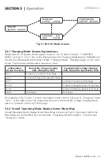
Page 99: ...ging Bulk Absorption Float Equalization E 4 Stage Charging Bulk Absorption Equalization Float N CC Constant Current CC Bulk Stage N CV Constant Voltage CV Absorption Stage E CC Constant Current CC Bulk Stage E CVA Constant Voltage Absorption CVA Stage E CVE Constant Voltage Equalization CVE Stage FLOAT Float Stage Float Stage For example in Fig 3 2 the 1st line of information under Column 4 Group ...

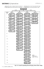
Page 100: ... 00V INVERTING OUTPUT POWER SAVING ID 1 RC XXX1 CHARGING GEN 4 STANDBY GEN 0 00V INVERTING OUTPUT CHARGING GEN 5 STANDBY 2014 10 16 16 00 12 000V 140 0A 0 0A 25 0C 0 00V 0 00V RC XXX1 50 00Hz 10 00A 2300W 2300VA PF 1 000 INVERTING OUTPUT CHARGING INPUT 10 00A N CC2 6 7 8 9 10 11 12 13 14 15 16 17 18 19 STANDBY ID 1 RC XXX1 INVERTING OUTPUT CHARGING INPUT CHARGING BAT EXT ò ò ò ò ò ò ò ò ò ò ò ò ò ...

Page 101: ...ge Charging N CC Constant Current CC Bulk Stage N CV Constant Voltage CV Absorption Stage E CC Constant Current CC Bulk Stage E CVA Constant Voltage Absorption CVA Stage E CVE Constant Voltage Equalization CVE Stage FLOAT Float Stage Float Stage 19 Screens Screen Nos 1 to 19 for CHARGING Mode Column 4 Group 3 are shown as an example for Bulk Charging Stage in Normal Charging Mode N CC Depending up...

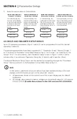
Page 102: ...NG online For 2 sec For 2 sec In Online Mode the top line of the display screen will alternate as follows to show that the unit is in Online Mode STANDBY STANDBY online For 2 sec For 2 sec INVERTING INVERTING online For 2 sec For 2 sec POWER SAVING POWER SAVING online For 2 sec For 2 sec CHARGING N CC CHARGING online For 2 sec For 2 sec 4 0 GROUP AND PARAMETER SETUP MENUS Up to 52 operating parame...

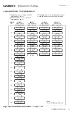
Page 103: ... 1 60 cycles DETECT TIME 1 300 cycles 4 FLOATING VOLTAGE 13 50 V HIGH CUT OFF 55 00 Hz CUT OFF VOLT 2 170 0 V 5 COMPENSATE 4 mV C C LOW CUT OFF 45 00 Hz DETECT TIME 2 60 cycles 6 7 8 9 10 11 12 13 14 BATT OVER VOLT 16 00 V LOW RESET 46 00 Hz CUT OFF VOLT 3 160 0 V ò ò ò ò ò ò ò ò ò ò ò ò ò ò ò ò ò HIGH RESET 54 00 Hz ò ò ò ò ò ò ò ò ò ò ò ò ò ò ò ò ò ò ò ò ò ò ò ò ò ò ò ONLINE OPTION 0 Option 1 ò ...

Page 104: ...ward pointer because Screen Nos in this Parameter Setting Menu Map decrease in the upward direction 1 GROUP 5 SELECT GROUP OTHER FUNCTION GROUP 6 SELECT GROUP TIME SETTING GROUP 7 SELECT GROUP STOP SD CARD POWER SAVING 0 Disable TIME SETTING 2000 01 01 00 00 STOP SD CARD 0 No BUZZER 1 On DISCHARGE BEEP 0 Off DEFAULT RESET 0 No DATA LOG TIME 1 1 sec PARAMETER SAVE 0 No 2 ENTER POINT 4 W 3 WAKE UP P...

Page 105: ...highly recommended to set the EVOTM Date and Time Parameter Group 6 as this value is used to record data logging files Refer to Section 4 9 for Date and Time set up Group 1 Any Operationg Mode Screen from Fig 3 2 Parameter Setup Screen eg BULK CURRENT Select Group Menu Map SELECT GROUP CHARGE CURVE BULK CURRENT 40 A INVERTING OUTPUT 230 00V SELECT GROUP STOP SD CARD Group 2 SELECT GROUP INPUT SETT...

Page 106: ...ress the Enter Key momentarily to write the desired numerical value for the 2nd digit The overall numerical value of the parameter will be selected after scrolling to the desired numerical value for the last digit Now press the Enter Key HOLD for 3 to 4 sec and then release Process for writing the overall numerical value of the parameter into the memory will be initiated the screen will display me...

Page 107: ...ROUP CHARGE CURVE Fig 4 1 Default current setting of 40A or previously set value will be displayed Press Enter Key to change Bulk Current parameter setting A Password will be requested KEY IN PASSWORD 0000 SELECT GROUP CHARGE CURVE BULK CURRENT 40 A PASSWORD CORRECT PASSWORD ERROR BULK CURRENT 40 A BULK CURRENT 90 A WRITING 50 A WRITE SUCCESS 50 A WRITE FAILURE 50 A OUT OF RANGE 90 A Password cons...

Page 108: ...iting to the inverter KEY IN PASSWORD 0000 SELECT GROUP CHARGE CURVE BULK CURRENT 40 A PASSWORD CORRECT PASSWORD ERROR BULK CURRENT 40 A BULK CURRENT 90 A WRITING 50 A WRITE SUCCESS 50 A WRITE FAILURE 50 A OUT OF RANGE 90 A BULK CURRENT 50 A Flashes twice when writing is successful KEY IN PASSWORD 0000 SELECT GROUP CHARGE CURVE BULK CURRENT 40 A PASSWORD CORRECT PASSWORD ERROR BULK CURRENT 40 A BU...

Page 109: ...Equalization Voltage 14 0V 16 0V 28 0V 32 0V 14 4V 28 8V 4 FLOATING VOLTAGE Float Voltage 13 0V 15 0V 26 0V 30 0V 13 5V 27 0V 5 COMPENSATE Temperature Compensation 3mV to 5mV C Cell 4mV C Cell 6 BATT OVER VOLT Battery Over Voltage Shut Down 14 0V 17 0V 28 0V 35 0V 16 0V 32 0V 7 RESET VOLTAGE Battery Low Voltage Reset 12 0V 17 0V 24 0V 35 0V 14 0V 28 0V 8 LOW VOLT ALARM Battery Low Voltage Alarm 9 ...

Page 110: ...In case External Solar Charge Controller is also charging the batteries through DC input terminals marked EXT Charger 3 4 in Fig 2 1 in Owner s Manual for EvolutionTM Series Inverter Charger the amount of Bulk Charging Current produced by the internal Battery Charging Section is adjusted in real time to satisfy the following condition Internal Bulk Charging Current Programmed Value of Bulk Current...

Page 111: ...ensation for the battery The operational range of the EVOTM Inverter Charger is 20 C to 60 C This compensation voltage will affect the Absorbtion Voltage Equalize Voltage Floating Voltage Batt Over Volt Restart Voltage Low Volt Alarm Batt Low Voltage when the Temperature Sensor is installed on the battery see Fig 2 5 in the Owner s Manual for EvolutionTM Series Inverter Charger SELECT GROUP CHARGE...

Page 112: ...VE BULK CURRENT 40 A RESET VOLTAGE 14 0 V Enter Key ò Up Key x 6 ò RESET VOLTAGE 14 0 V ò KEY IN PASSWORD 0000 Enter Key ò Password 8052 See Section 4 3 1 LOW VOLT ALARM When inverting if battery voltage is under the set value the Red LED marked Fault flashes once per second The buzzer in EVOTM Inverter Charger will beep once per second If Relay Function is set for Generator the relay will turn ON...

Page 113: ...n battery voltage as a result of high power short duration AC loading e g motor starting inrush current etc a timer is used to qualify BATT LOW VOLTAGE condition only if the battery voltage drops to or below the set BATT LOW VOLTAGE threshold for the set LV DETECT TIME The timer starts as soon as the battery voltage drops to the set threshold of BATT LOW VOLTAGE described above SELECT GROUP CHARGE...

Page 114: ...ION This setting is effective only when Online Mode is selected ONLINE MODE 1 On as per sub section titled ONLINE MODE above The default setting is 0 Option 1 Programming steps are given below SELECT GROUP CHARGE CURVE BULK CURRENT 40A ONLINE OPTION 0 Option 1 Enter Key ò Up Key x 13 ò ONLINE OPTION 0 Option 1 ò KEY IN PASSWORD 0000 Enter Key ò Password 8052 See Section 4 3 1 Details of the two op...

Page 115: ...TAGE up to the programmed value of Absorption Voltage If the programmed value of absorption Voltage is the RESET VOLTAGE due to continuation of charging for the pro grammed value of GEN OFF TIME after the voltage has reached the programmed value of RESET VOLTAGE and ii the battery may not be charged fully after the Transfer Relay has de energized because the programmed values of RESET VOLT AGE and...

Page 116: ...ELECT GROUP CHARGE CURVE BULK CURRENT 40A GEN ON TIME 60 min Enter Key ò Up Key x 16 ò GEN ON TIME 060 min ò KEY IN PASSWORD 0000 Enter Key ò Password 8052 See Section 4 3 1 GEN OFF DELAY This parameter is a Programmable Timer 0 240min Default 60 min that is used for the following Programming Automatic Starting and Stopping of Generator Section 4 8 under Relay Function 3 Generator 1 The Timer sets...

Page 117: ...nt and the pass through load current Based on the rated capacity of the Grid Branch Circuit Generator the net AC input current will be required to be limited to prevent overloading of the Grid Branch Circuit Generator EVOTM Series has a very powerful battery charger that will require a proportionate higher AC input current from the Grid Generator The Grid Branch Circuit Generator will also be requ...

Page 118: ...OW CUT OFF value when in Charging Mode the EVOTM Inverter Charger will transfer to Inverting Mode SELECT GROUP CHARGE CURVE SELECT GROUP INPUT SETTING LOW CUT OFF 45 00 Hz DEFAUT FREQ 0 50 Hz Up Key ò Enter Key ò Up Key x 5 ò LOW CUT OFF 45 00 Hz ò KEY IN PASSWORD 0000 Enter Key ò Password 8052 See Section 4 3 1 LOW RESET This is the reset frequency at which the unit will revert to Charging Mode a...

Page 119: ...t voltage falls below CUT OFF VOLT 2 for period DETECT TIME 2 the EVOTM Inverter Charger will transfer to Inverting Mode SELECT GROUP CHARGE CURVE SELECT GROUP INPUT LOW LIMIT CUT OFF VOLT 2 170 0 V RESET VOLTAGE 190 0 V Up Key x 2 ò Enter Key ò Up Key x 3 ò CUT OFF VOLT 2 170 0 V ò KEY IN PASSWORD 0000 Enter Key ò Password 8052 See Section 4 3 1 DETECT TIME 2 This is the time limit in cycles up t...

Page 120: ...r Key ò Password 8052 See Section 4 3 1 CUT OFF VOLT 1 If during Charging Mode the AC input voltage rises above CUT OFF VOLT 1 for period DETECT TIME 1 the EVOTM Inverter Charger will transfer to Inverting Mode SELECT GROUP CHARGE CURVE SELECT GROUP INPUT HIGH LIMIT CUT OFF VOLT 1 265 0 V RESET VOLTAGE 260 0 V Up Key x 3 ò Enter Key ò Up Key x 1 ò CUT OFF VOLT 1 275 0 V ò KEY IN PASSWORD 0000 Ente...

Page 121: ...ARGE CURVE SELECT GROUP INPUT HIGH LIMIT DETECT TIME 3 1 cycle RESET VOLTAGE 260 0 V Up Key x 3 ò Enter Key ò Up Key x 6 ò DETECT TIME 3 0001 cycle ò KEY IN PASSWORD 0000 Enter Key ò Password 8052 See Section 4 3 1 4 8 GROUP 5 PARAMETER SET UP OTHER FUNCTIONS Please refer to Parameters under Group 5 at Fig 4 2 Details of Parameter set up are given below TABLE 4 8 Group 5 Parameter Set Up OTHER FUN...

Page 122: ... POWER SAVING 1 Enable Up Key x 4 ò Enter Key ò Up Key x 2 ò WAKE UP POINT 07W ò KEY IN PASSWORD 0000 Enter Key ò Password 8052 See Section 4 3 1 REMOTE SWITCH This selection is used when ON OFF control of EVOTM Inverter Charger is desired through external 12 VDC signal fed to Remote ON OFF terminals on the Front Panel of EVOTM Inverter Charger 15 Fig 2 1 in EVOTM Inverter Charger Owner s Manual O...

Page 123: ...lay are connected to 3 terminals of Terminal Block 14 Fig 2 1 in Owner s Manual for EvolutionTM Series on the front panel The contacts are marked NO Normally Open Common and NC Normally Closed When the Status Relay is OFF de energized contacts marked Common and NO will be in open condition and contacts marked Common and NC will be in closed condition When the Status Relay is ON energized contacts ...

Page 124: ...and NO terminals are wired to the optional Generator Auto Start Stop Control Module which in turn is wired to the Remote Start Stop connections on the Generator The AC output terminals of the Generator are wired to the Generator Input Terminals on the EVOTM 7 8 9 in Fig 2 3 in Owner s Manual for EVOTM Series Inverter Charger For installation details please refer to Section 3 15 Fig 3 13 and Sectio...

Page 125: ...ut from the Generator switches OFF EVOTM will change over to Inverting Mode NOTE The battery will be charged to 100 State of Charge after the Transfer Relay has de energized on entering Float Stage 3 Generator 1 This Function will start the Generator at LOW VOLT ALARM and stop the Generator when the batteries are charged to the desired programmed level of voltage RESET VOLTAGE and stay at this des...

Page 126: ...ter the Status Relay has been switched OFF de energized and Generator is stopped will be indeterminate Diagram showing steps for programming the above RELAY FUNCTION is given below SELECT GROUP CHARGE CURVE SELECT GROUP OTHER FUNCTION RELAY FUNCTION 2 Generator 0 POWER SAVING 1 Enable Up Key x 4 ò Enter Key ò Up Key x 4 ò RELAY FUNCTION 2 Generator 0 ò KEY IN PASSWORD 0000 Enter Key ò Password 805...

Page 127: ...d from Year 2000 to 2099 only Month can be programmed from 01 to 12 only Day can be programmed from 01 to 31 only Hour can be programmed from 00 to 24 only Minute can be programmed from 00 to 60 only If the numbers Entered for Month Day Hour and Minute are not within the above ranges message OUT OF RANGE will be displayed and the display screen will go back to the previously set time Setting proce...

Page 128: ...g can be disabled and data logging times can be selected using Parameter Setting Mode under Other Functions See Section 4 8 and Table 4 8 under heading DATALOG TIME and DATALOG DISABLE When the SD card is inserted and Data Logging Function is enabled Default the EVOTM Inverter Charger will start recording statistics and events on the card SD card detected V2 x xxGB SD card unusable SD card Read er...

Page 129: ...s contents opened with a general purpose Text Reader The First Row is Inverter Model the Second Row is the title of columns separate by TABLE 5 2 Contents of Data Log File Follow procedure given below to open Data Log Files in Excel Start Excel Click File Menu Button Microsoft Office Button on the left hand corner Click Open from the Drop Down Menu Navigate to the Directory where the Log Files dow...

Page 130: ...rrent Output VA Output Watt Battery Volt Battery Current External Current Battery Temp Transformer Temp Bus Bar Temp Heat Sink Temp Fan Speed Mode Error Code Charge Stage Event Fig 5 1 Screen Showing txt Files Click Open Button Bottom right corner of Fig 5 1 Text Import Wizard Step 1 will be shown Fig 5 2 Choose Delimited File Type Fig 5 2 Screen Shot of Step 1 of Text Import Wizard in Excel Secti...

Page 131: ...ee Fig 5 3 Choose Semicolon and click Finish button Fig 5 3 Screen Shot of Step 2 of Text Import Wizard in Excel Data as in Fig 5 4 will be displayed on your Worksheet with the Log Data stored in Columns and Rows Fig 5 4 Screen Shot and Data Log Work Sheet Section 5 SD Card ...

Page 132: ...p Key x 4 ò Enter Key ò Up Key x 10 ò ò KEY IN PASSWORD 0000 Enter Key ò PARAMETER SAVE 1 Yes Up Key ò PARAMETER SAVE 0 No ò Saved file end Press Enter Key hold for 3 to 4 sec and release ò Password 8052 See Section 4 3 1 Now select PARAMETER SAVE 1 Yes Saved file end PARAMETER SAVE 0 No The parameters will be saved and message PARAMETER SAVE 1 Yes Saved file end will be seen and then the screen w...

Page 133: ...e tion of Power Off Sequence after Power ON OFF Button is pressed for 5 sec ON ON OFF Normal charging Flash 1 time per second OFF OFF Equalization charging Flash 2 times per second OFF OFF Inverting ON OFF Beep per 3 second Default OFF Low battery alarm ON Flash 1 time per second Beep per second Power saving Flash 1 time per 3 second OFF OFF Standby OFF OFF OFF Fault OFF ON ON NOTE 1 Buzzer is ava...

Page 134: ...ndition will be cleared While in Battery low voltage fault condition if AC input is made available before the expiry of LV CUT OFF TIME the Battery low voltage fault condition will be cleared The EVO TM Inverter Charger will restart in Inverter Mode synchronize with the AC input and then transfer to the AC input at zero crossing It will now operate in Charging Mode Battery ultra low voltage EVO TM...

Page 135: ...anual reset by powering OFF waiting for 1 minute and then powering ON again The set threshold of GRID MAX CURRENT GEN MAX CURRENT Section 4 5 should match the breaker capacity of the AC input source AC input Branch Circuit If AC input current capacity cannot be increased reduce the AC load BULK CURRENT Section 4 4 accordingly Output over current EVO TM Inverter Charger is in FAULT MODE because the...

Page 136: ...former in the EVO TM Inverter Charger has overheated to 150 C The Green LED marked Status will be switched OFF and the Red LED marked Fault will be steady ON The buzzer in EVO TM Inverter Charger will beep steady If in Inverting Mode Inverter Section will be switched OFF If in Charging Mode the Transfer Relay will be de energized and the Inverter Section will be switched OFF Check that the fans ar...

Page 137: ...AY 2 Rows 16 Character each Alpha Numeric LCD Display LED INDICATORS Green Status Red Fault Alarm INPUT OUTPUT CONNECTION CABLE SET RJ 45 Data Cable Straight Wired 10 Meters 33 ft ENVIRONMENT OPERATING TEMPERATURE RANGE 20 C to 60 C DIMENSIONS W X H X D MM 144 x 114 x 35 5 W X H X D INCHES 5 6 x 4 5 x 1 4 WEIGHT WEIGHT WITHOUT CABLE 0 2 kg 0 4 lb WEIGHT WITH CABLES 0 5 kg 1 2 lb Section 8 Specific...

Page 138: ... number that has been altered removed or modified in any way There is no warranty for defects or damages to equipment or parts caused by Installation alternation inspection or removal Normal wear and tear Abuse or misuse of the equipment including exposure to excessive heat salt or fresh water spray or water immersion Corrosion fire lightening biological infestations or Acts of God Repairs attempt...

Page 139: ...SAMLEX AMERICA INC 49 APPENDIX A Notes ...

Page 140: ...oll Free Numbers Ph 1 800 561 5885 Fax 1 888 814 5210 Local Numbers Ph 604 525 3836 Fax 604 525 5221 Website www samlexamerica com USA Shipping Warehouses Kent WA Plymouth MI Canadian Shipping Warehouse Delta BC Email purchase orders to orders samlexamerica com ...

Reviews: