Index revision : A
1
7143
User manual
SAMES KREMLIN
SAS -
13, Chemin de Malacher - 38240 MEYLAN - FRANCE
Tel. 33 (0)4 76 41 60 60 - www.sames-kremlin.com
Inobooth
Page 1: ...Index revision A 1 7143 User manual SAMES KREMLIN SAS 13 Chemin de Malacher 38240 MEYLAN FRANCE Tel 33 0 4 76 41 60 60 www sames kremlin com Inobooth...
Page 2: ...ing courses in the operation and maintenance of your equipment A catalogue is available on request Choose from a wide range of courses to acquire the skills or knowledge that is required to match your...
Page 3: ...cs 15 3 2 Noise level 15 3 2 1 Inobooth in operation phase 15 3 2 2 Inobooth in cleaning phase 15 3 3 Pneumatic diagram 16 3 4 Manual station Dimensions mm 17 3 4 1 Weight and dimensions 17 4 Starting...
Page 4: ...4 2 19 Before starting up the booth 30 5 Maintenance 31 5 1 Maintenance summary table 31 5 2 Cleaning 31 5 2 1 Procedure A1 Booth interior cleaning 31 5 2 2 Procedure A2 Booth exterior cleaning 32 5 2...
Page 5: ...ottom right must be completed by the integrator in accordance with the instructions below R f rence note either the drawing number the customer s name or the project number Type de cabine note either...
Page 6: ...e listed in the table below Risks Gravity Frequency and exposure time Means used work to limit the damage Noise during the cleaning phases for noise level measurement see 3 2 page 15 Serious 0 to 10 t...
Page 7: ...ooth and on the roof 1 5 Warnings DANGER It is imperative that anyone wearing a pacemaker does not use the equipment and does not enter the projection area High voltage can cause the pacemaker to malf...
Page 8: ...f less than 5 meters from the powder station is prohibited if the following safety measures are not obser ved The booth must be protected by a cover made of non flammable or hardly flam mable material...
Page 9: ...m the powder projection can only be done if the ventilation of the booth is in operation 22 Access to the inside of the booth is only allowed to personnel who have been warned of the risks of shocks l...
Page 10: ...tion incorrect use failure to follow procedures use of a control system not designed by SAMES KREMLIN or a SAMES KREMLIN control system modified by a third party without written permission from an aut...
Page 11: ...owder by the central supply unit or any other powder con tainer and set in motion by mechanized systems Optional manual powder coating stations dedicated compartments placed at the entrance and or exi...
Page 12: ...booth Suction shutter Movable shutters for powder suction Bottom of booth Rigid booth bottom structure Cylinders Allows the opening and closing of the suction shutters during the cleaning phase Emerg...
Page 13: ...cement profile for fastening to the booth roof Side panel Roof support side structure Suction shutter control Controls the opening of the booth s suction shutters only one control per installation Pla...
Page 14: ...obooth Overall length 2606 mm Overall width 1924 mm Height A From 2500 to 3300 mm Pattern of the parts to be coated Max width 800 mm Max height 2300 mm Body dimensions Max width 850 mm Max height 2495...
Page 15: ...der the specified ope rating conditions Measuring conditions the equipment was put into operation at maximum characteristics the measurements were carried out at different positions at 1 m from the po...
Page 16: ...R1 QR2 Shutter opening Shutter closing Shutter closing Shutter opening 8 10 8 10 4 6 VENTILATION SHUTTER VENTILATION SHUTTER 20A 20A 20A 20A 20A 20A 20A 20A 20A 411A 412A 411A 411A 412A 412A 8 10 LEFT...
Page 17: ...ight and dimensions Option Manual station Platform length 1495 mm Length with fastening bar 3971 mm Platform width 1816 mm Exterior width with stairs 2391 mm Height A From 2500 to 3300 mm Approximate...
Page 18: ...Description Qty Unit of sale 1407150 Drilling jig tool for blowing nozzles 1 1 Part Number Description Qty Unit of sale 900019088 Side panel lifting plate 2 1 Part Number Description Qty Unit of sale...
Page 19: ...nimum length of 1 meter Screw machine with tips Gazelle stepladder 4 2 Installation WARNING These assembly procedures must be carried out by at least two authorized persons 4 2 1 Installation of the b...
Page 20: ...tly horizontal First adjust the four outer support feet 2 and then unscrew the other support feet until they are in contact with the floor WARNING It is imperative to correctly adjust the height of th...
Page 21: ...he flap positions correctly according to the diagram below Step 1 position a shutter 1 in the box 4 and simultaneously insert the axles 2 on each side of the shutter Step 2 Attach the axles to the hou...
Page 22: ...d lock it with two clips Step 4 Attach the support 6 to the flange 5 with 4 M6 x 20 bolts with nuts and washers Step 5 Install the elbow fitting 3 on the cylinder 4 Step 6 Screw the rod cover 2 onto t...
Page 23: ...cover 1 to the housing 2 with 8 self drilling 4 8 x 22 screws 3 4 2 6 Installation of the side panels Step 1 Position the longitudinal 3 and entry exit 2 profiles on the box 1 WARNING As the panels h...
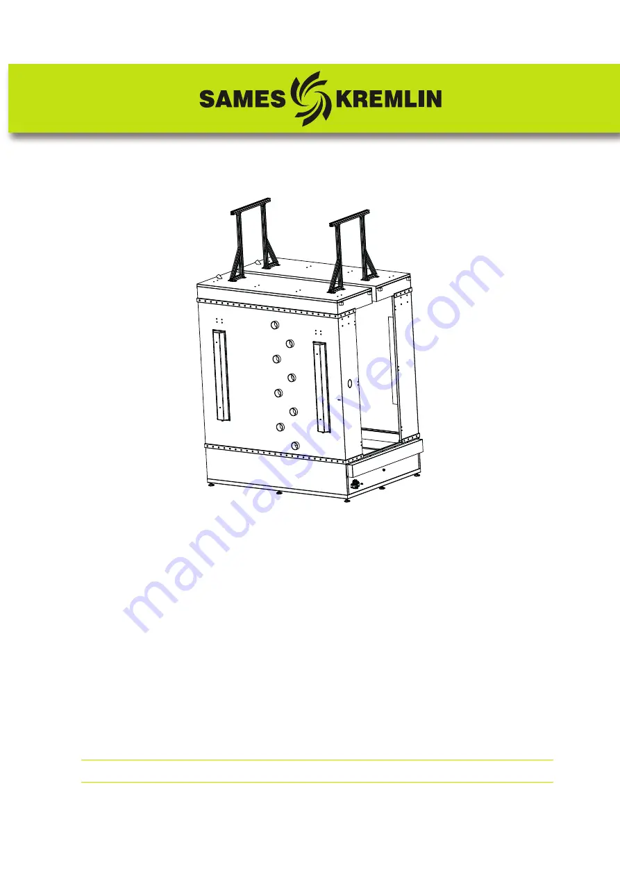
Page 24: ...2 7 Installation of roofs Step 1 Place the roofs 1 on the side panels 3 Step 2 Screw the side profile plates 4 and the entry exit plates 2 with 66 M8 x 16 screws Step 3 Fix the fire detectors 5 to th...
Page 25: ...e there is a clearance of 3 mm all around the door Step 4 Lock the brace spacings Step 5 Tighten the side panels permanently to the bottom box 4 2 9 Lighting installation Step 1 Place the seal 2 on th...
Page 26: ...e circular openings for the projectors fitted to the Inoprofile Place the blower rings 2 on the edges of the cir cular opening and secure the ring with a M6 x 10 grub screw 1 4 2 12 Installation of th...
Page 27: ...e powder projectors user manual see RT Nr 7133 4 2 15 Inobooth electrical connections control cabinet From the control cabinet carry out the electrical connections for the following equipment Blowing...
Page 28: ...he seal 1 along the booth ope ning before pressing the floor frame assembly against the booth Step 5 Level the frame 3 by adjusting the four outer support feet 4 then unscrew the other support feet un...
Page 29: ...and with 4 screws and washers M10 x 60 on the side panel 3 Step 10 Fix the booth support profile 6 on the left roof 4 with 4 screws and washers M8 x 25 and then fix the profile on the booth roof with...
Page 30: ...tion Step 18 Repeat the operation for the other lighting Step 19 Fix the support of the pneumatic cylin der control 1 on the guardrail 2 with 2 screws M6 x 14 Step 20 Connect the pneumatic hoses to th...
Page 31: ...lean the booth as the booth lining is made of PVC there is a risk of accumulation of electrostatic charges that can cause a spark and ignite the solvent Do not spray any cleaning agent into the booth...
Page 32: ...ning Once a year clean the exterior of the booth with PS 1098 P N 100000037 recommended by SAMES KREMLIN Follow the procedures described below Required material Clean lint free cloths Cleaning agent P...
Page 33: ...43 5 2 3 Procedure A3 Check the proper operation of the suction shutters Every three months check the proper operation of the suction shutters and check the condi tion of the pneumatic distribution eq...
Page 34: ...pment be sure to thoroughly clean all components Refer to the safety rules see 1 page 5 before any intervention Items Material 3 11 12 15 19 Plastic material 2 4 7 14 18 PVC honeycomb 5 8 10 Steel 6 1...
Page 35: ...Remedies No cleaning of a projector No air supply Restore the compressed air supply Air solenoid valve out of order Replace the air solenoid valve Poor cleaning of the walls Unsuitable cleaning produc...
Page 36: ...Cylinder axis support 2 1 3 3 180000528 Rod cap 2 1 3 4 180000525AT Cylinder Dia 40 C 200 2 1 2 5 180000527 Front swivel flange 2 1 3 6 180000526 Rear swivel flange 2 1 3 7 220000547 Distributor 1 1...
Page 37: ...ve maintenance Level 2 Corrective maintenance Level 3 Exceptional maintenance Item Part Number Description Qty Unit of sale Mainte nance level for spare parts 1 R3PVPR167 2 2 way valve 1 1 1 2 J2CTTL2...
Page 38: ...2 Corrective maintenance Level 3 Exceptional maintenance Item Part Number Description Qty Unit of sale Mainte nance level for spare parts 910003039 Cleaning rod handle 1 1 3 1 F1RBTU179 3 8 ball valv...
Page 39: ...Item Part Number Description Qty Unit of sale Mainte nance level for spare parts 910003024 Cleaning rod Length 1 m 1 1 3 1 900002261 Cleaning nozzle 1 1 2 2 X3ASSC686 Zinc coated Hc cup M6 x 6 screw...
Page 40: ...Item Part Number Description Qty Unit of sale Mainte nance level for spare parts 910030166 Cleaning rod Length 2 2 m 1 1 3 1 900019718 Cleaning nozzle 1 1 2 2 X3ASSC686 Zinc coated Hc cup M6 x 6 scre...
Page 41: ...Index revision A 41 7143 8 Revision index History Rev Date Description Modification locating A 02 2021 First Issue...