Operator's manual
Tractor sweeper
MOP
- 14 -
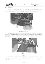
Fig. 14. Side brush mounting points
1 - holes
∅
11 for brush arm mounting bolts. 2 - holes
∅
11 for arm guide assembly bolts. 3 - bracket for
mounting three-way distributor for hydraulics operation control.
If items „1” and „3” above meet installation requirements, unlike item „2” only, an adequate
arm guide can be purchased at the sweeper's manufacturer as a spare part (see: parts catalogue).
The side brush installation set is comprised of all the items specified in the parts catalogue.
All footnotes regarding assembly parts are in reference to items in Table 5 of the sweeper's parts
catalogue.
Before approaching the installation, prepare any tools necessary for this task to provide a
problem-free installation of the side brush on the sweeper:
two flat wrenches size: 10, 17, 19 (possibly flat wrench and ring/socket wrench);
one flat wrench: 27.
To install a side brush set the sweeper on an even, paved ground, and then proceed as follows
on Fig. 15:
1)
Dismount the original mounting bracket of the container on the left and install left bracket of
the container (it. 1) delivered with the side brush.
2)
Install mounting (it. 2) on the sweeper's body side wall with bolts M10x30 (4 pcs).
3)
Mount side brush arm (it. 3) on mounting pivot (it. 2) and secure the arm with washer fi 40
(it. 9) and bolt M12x35.
4)
Mount the arm guide (it. 4) on the container mounting bracket with bolts M10x70 (2 pcs).
5)
Lift the brush arm above the first lower hole on the arm guide to install bolt M12x100 with
spacer tube (it. 10), and then in any next available hole insert and secure cotter pin set (it.
12). The cotter is used to adjust the brush height while operating.
6)
Install the head with the side brush (pre-assembled unit: motor base, hydraulic motor,
mounting plate set and side disc brush) with bolt M12x110, spacer tube II (it. 11) and bolt
M12x120.
7)
Install hydraulic hoses for: supply (it. 21), return (it. 22) to reduction coupling body (it. 15)
on hydraulic motor (it. 14).
1
3
2


