


SAM4S ER-600 SERIES
11-1
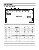
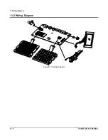
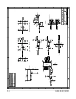
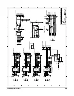
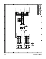
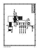
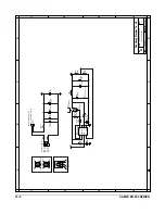
11 Wiring Diagram
11-1 Wiring Pin Connection
CN16=LCD
CN2=DRAWER
CN9=IRC
CN5,CN6=RS232
NO
SIGNAL NAME
NO
SIGNAL NAME
NO
SIGNAL NAME
NO
SIGNAL NAME
1 VSS 1 GND 1
TPTX(-)
1 N.C
2 VDD 2
DRAWER1_OUT
2
TPTX(-)
2 RXD0
3 VCONTRAST 3
SENDWRCOMP1_IN
3
GND
3
TXD0
4 DATA/INST 4
VDRV
4
GND
4
DTR0
5 R/W 5
DRAWER1_OUT
5
TPTX(+)
5 GND
6 EN 6 GND 6
TPTX(+)
6 DSR0
7 D0 7 GND 7
TPTX(-)
7
Short
NO.4
8
D1
8 DRAWER2_OUT 8
TPTX(-)
8 Short
NO.6
9 D2 9
SEN_DWRCOMP2_IN
9 GND 9
VSERIAL
10 D3 10 VDRV 10 GND 10 FGND
11
D4
11 DRAWER2_OUT 11
TPTX(+)
11
FGND
12 D5 12 GND 12
TPTX(+)
13 D6
14 D7
CN13=MCR
CN7=RS232
CN8=RS232
15
CE1
NO
SIGNAL NAME
NO
SIGNAL NAME
NO
SIGNAL NAME
16 CE2 1 VCC 1 N.C 1
CN10(pin
NO.2)
17
CE3(192*64)
2 GND 2
DSR2
2
DSR3
18 nRESET 3 MCR_RDT1&2 3
TXD2
3
TXD3
19
VOUT
4 MCR_RCL1&2 4
RXD2
4
RXD3
20
N.C
5
MCR_CLS1&2
5
Short NO.8
5
short NO.8
21
BACKLIGHT VOL
6
MCR_RDT2&3
6
Short NO.2
6
Short NO.2
22 GND 7
MCR_RCL2&3
7 GND 7 GND
8
MCR_CLS2&3
8
DTR2
8
DTR3
CN1=MODE KEY
CN12=SMPS
CN3/4/11/14=KEYBOARD
CN15=SWITCH
MAIN BOARD
CN2
CN5 CN6
CN7 CN8
CN9
CN15
CN16
CN12
CN13
CN3 / 4
CN1
CN11 / 14
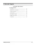
Summary of Contents for ER-600
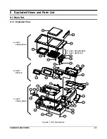
Page 48: ...8 Exploded Views and Parts List 8 6 SAM4S ER 600 SERIES MEMO...
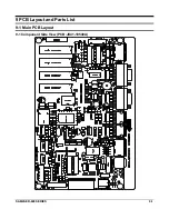
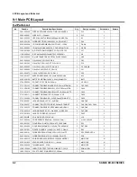
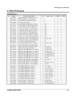
Page 54: ...9 PCB Layout and Parts List 9 6 SAM4S ER 600 SERIES MEMO...
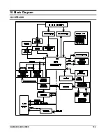
Page 55: ...SAM4S ER 600 SERIES 10 1 10 Block Diagram 10 1 ER 600...
Page 56: ...10 Block Diagram 10 2 SAM4S ER 600 SERIES MEMO...
Page 58: ...11 Wiring Diagram 11 2 SAM4S ER 600 SERIES 11 2 Wiring Diagram Figure11 1 Wiring Diagram...
Page 68: ...Shin Heung Precision FEBRUARY 2004 Printed in KOREA V1 1 Code No JK68 60935A...


