


5 Reference Information
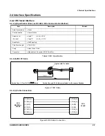
SAM4S ER-600 SERIES
5-5
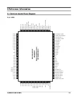
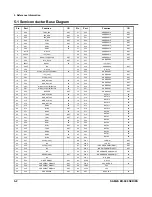
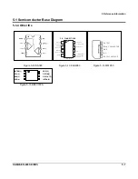
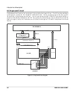
5-1 Semiconductor Base Diagram
5-1-3 Logic ICs
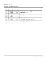
Figure 5-7 74HC245
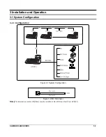
Figure 5-8 74HC541
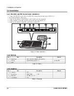
Figure 5-9 74HC574
A
DATA
PORT
A8
A7
A6
A5
A3
A4
A2
A1
9
8
7
6
5
4
3
2
DIRECTION
OUTPUT ENABLE
1
19
PIN 10 = GND
PIN 20 = V
CC
18
17
16
15
14
13
12
11
B1
B2
B3
B4
B5
B6
B7
B8
B
DATA
PORT
FUNCTION TABLE
Control Inputs
Output
Enable
Direction
Operation
L
L
Data Transmitted from Bus B to Bus A
L
H
Data Transmitted from Bus A to Bus B
H
X
Buses Isolated (High–Impedance State)
X = don’t care
18
Y1
2
A1
17
Y2
3
A2
16
Y3
4
A3
15
Y4
5
A4
14
Y5
6
A5
13
Y6
7
A6
12
Y7
8
A7
11
Y8
9
A8
OE1
OE2
1
19
Output
Enables
Data
Inputs
Noninverting
Outputs
PIN 20 = V
CC
PIN 10 = GND
L
L
H
X
L
L
X
H
L
H
X
X
Inputs
Output Y
OE1
OE2
A
L
H
Z
Z
X = Don’t Care
Z = High Impedance
FUNCTION TABLE
DATA
INPUTS
D0
2
19
Q0
D1
D2
D3
D4
D5
D6
D7
CLOCK
OUTPUT ENABLE
3
4
5
6
7
8
9
11
1
18
17
16
15
14
13
12
Q1
Q2
Q3
Q4
Q5
Q6
Q7
NONINVERTING
OUTPUTS
PIN 20 = V
CC
PIN 10 = GND
FUNCTION TABLE
Inputs
Output
OE
Clock
D
Q
L
H
H
L
L
L
L
L,H,
X
No Change
H
X
X
Z
X = Don’t Care
Z = High Impedance
Summary of Contents for ER-600
Page 48: ...8 Exploded Views and Parts List 8 6 SAM4S ER 600 SERIES MEMO...
Page 54: ...9 PCB Layout and Parts List 9 6 SAM4S ER 600 SERIES MEMO...
Page 55: ...SAM4S ER 600 SERIES 10 1 10 Block Diagram 10 1 ER 600...
Page 56: ...10 Block Diagram 10 2 SAM4S ER 600 SERIES MEMO...
Page 58: ...11 Wiring Diagram 11 2 SAM4S ER 600 SERIES 11 2 Wiring Diagram Figure11 1 Wiring Diagram...
Page 68: ...Shin Heung Precision FEBRUARY 2004 Printed in KOREA V1 1 Code No JK68 60935A...


