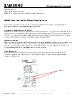
background image

5

www.salda.lt

RIRS 300VE EKO

Ptouch Remote controller 
Stouch Remote controller 
AF

Set of spare filters

SKG

Closing damper SKG

SKP

Actuator for damper

Ptouch Boîtier de commande
Stouch Boîtier de commande
AF

Filtre de rechange FR

SKG

Clapet SKG

SKP

Servomoteur du clapet

Ptouch Bedienpult 
Stouch Bedienpult 
AF

Ersatzfiltergarnitur

SKG

Luftklappe SKG

SKP

Klappenantrieb

Stouch

Ptouch

- L’installation ne doit être effectuée que par du personnel formé

et qualifi é.

- Le dispositif doit être installé sur une surface horizontale et

plate de sorte que le dispositif ne penche pas (Fig. 01).

- Suivre les indications indiquées sur le caisson de la centrale

pour raccorder les gaines de ventilation.

- Avant le raccordement des gaines de ventilation, les piquages

du dispositif de ventilation doivent être fermés.

- En cas de besoin, il est possible de changer le côté « service »

du dispositif.

- En raccordant les gaines de ventilation, faire attention aux

directions de fl ux d’air indiquées sur le panneau de la centrale.

- Ne pas raccorder de coudes près des piquages de raccorde-

ment

de la centrale. La distance minimale du conduit d’air

droit entre le dispositif et la première branche de conduits d’air

doit être de 1xD sur l’air repris, 3xD au souffl age, où D est le

diamètre des gaines de ventilation.

- Pour le raccordement de la centrale à la gaine de ventilation,

nous conseillons d’utiliser des accessoires comme des man-

•  Installation works shall be performed only by trained and qualified 

personnel.

•  Unit shall be installed firmly and tightly to ensure safe operation.

•  Appropriate accessories must be used for wall mounting of the unit 

as indicated in (Pic. 1). The unit must be installed in the manner to 

avoid its leaning.

•  Before connecting to the air duct system, the connection openings of 

ventilation system air ducts shall be closed.

•  When  connecting  air  ducts,  consider  the  direction  of  air  flow 

indicated on the casing of the unit.

•  Do not connect the elbows near the connection flanges of the unit. 

The minimum distance of the straight air duct between the unit and 

the first branch of the air duct in the suction air duct must be 1xD, in 

air exhaust duct 3xD, where D is diameter of the air duct.

•  Installation  shall  be  performed  in  such  manner  that  the  weight  of 

the  air  duct  system  and  its  components  would  not  overload  the 

ventilation unit.

•  2xL (where L is the depth of the unit) of space must be left during 

installation for opening of the maintenance door of the ventilation 

unit (Pic. 2).

•  If the installed ventilation unit is adherent to the wall, it may transmit 

•  Die Montagearbeiten dürfen nur von geschultem und qualifizier-

tem Personal ausgeführt werden.

•  Das Gerät ist fest und starr zu montieren, damit ein sicherer Be-

trieb gewährleistet ist.

•  Bei der Montage des Gerätes an eine Wand sind die dafür be-

stimmten Zubehörteile zu verwenden (Abb. 1). Das Produkt ist 

nicht geneigt zu montieren.

•  Vor  dem Anschließen  an  das  Luftleitungssystem  sind  die An-

schlussöffnungen für Luftleitungen abzudecken.

•  Beim Anschließen der Luftleitungen ist auf die am Gerätegehäu-

se angegebenen Luftströmungsrichtungen zu achten.

•  Schließen Sie keine Bögen in der Nähe von Geräteanschluss-

stutzen an. Der Mindestabstand einer geraden Luftleitung zwi-

schen dem Gerät und der ersten Abzweigung in der Zuluftleitung 

muss 1xD, in der Abluftleitung 3xD betragen (D - Durchmesser 

der Luftleitung).

•  Die Montage ist so durchzuführen, dass durch das Gewicht des 

Luftleitungssystems und aller seiner Bauteile keine Belastungen 

am Lüftungsgerät auftreten.

•  Bei der Montage ist ein Freiraum in Größe von 2xL (L - Tiefe des 

Summary of Contents for RIRS 300VE EKO

Page 1: ...ehalten Subject to technical modification RIRS 300VE EKO_P0033_AL_0002 RIRS 300VE EKO CENTRALES DE TRAITEMENT D AIR AVEC R CUP RATION DE CHALEUR AIR HANDLING UNITS WITH ROTOR HEAT EXCHANGER L FTUNGSAN...

Page 2: ...tbedingungen standhalten k nnen Nach Auspacken des Ger tes berpr fen Sie ob es beim Trans port nicht besch digt wurde Besch digte Ger te d rfen nicht montiert werden Die Verpackung ist nur eine Schutz...

Page 3: ...n f hren Bei Montage und Wartung des Ger tes tragen Sie spezielle Ar beitskleidung Vorsicht Kanten des Ger tes und seiner Bestand teile k nnen scharf sein und Verletzungen zuf gen Tragen Sie am Ger t...

Page 4: ...gsseite ge ndert wer den d h es kann entweder mit der linken oder der rech ten Au enluftzufuhr montiert werden Dies erfolgt durch Ver tauschen der hinteren T r mit der vorderen T r Standardm ig wird d...

Page 5: ...avoid its leaning Before connecting to the air duct system the connection openings of ventilation system air ducts shall be closed When connecting air ducts consider the direction of air flow indicat...

Page 6: ...be insulated additionally in order to decrease the noise and vibrations Also the wall mounting accessories must be insulated from the potential transfer of the vibration If there is a possibility for...

Page 7: ...r K chenhaube und des L ftungsger tes sowie der elektrische Kontakt des Steuerkreises sichergestellt sein Weitere Ger temontage erfolgt gem der Beschreibung im Ka pitel Mechanische Montage Merkmale Zu...

Page 8: ...e motor of heat exchanger and the electric heater are switched on the speed of fans is reduced The speed is reduced while the air temperature is maintained by electric heater The speed is increased wh...

Page 9: ...M2 N L L PE PE N N L L 1 2 3 8 7 6 5 4 X6 KH PE L N Q 9 K4 9 X6 KH RP2 RP4 max RP3 RP5 mid RP1 RP6 min 12V L N PE 1 2 3 8 7 6 5 4 3 1 P COOLING VAL 24V VAL p mA GND GND Alarm Watter CO2 Pressure Roto...

Page 10: ...mperature is lower than the set temperature the motor of the rotor heat exchanger is switched on The electric heater is switched on before the set temperature is reached If the supply air temperature...

Page 11: ...Einstellung der Str mungen wird von au en des Aggregats vorgenommen Ziehen Sie die Platine VP control Abb QW1 aus der Hauptplatine VP300GR 1 Abb QW2 Verbinden Sie die Platinen mit dem Kabel VP cabel m...

Page 12: ...carte de contr le automatique Avant la mise en marche de l installation de ventilation il est n cessaire de s assurer de l application des instructions de s curit et de fonctionnement nonc es ci dess...

Page 13: ...teur de l changeur de chaleur est d connect Le compresseur de la section de l changeur de chaleur rotatif est desserr et l changeur de chaleur retir Fig 4 a b et c L changeur de chaleur est nettoy ave...

Page 14: ...ern mit einem sanften nicht l senden und keine Korrosion verursachenden Reinigungsmittel mit Wasser Zum Reinigen des Fl gelrads verwenden Sie keine Hochdruck reiniger Scheuermittel scharfen Instrument...

Page 15: ...k if fuses in control board are not blown Check the connections Reduced air flow Check the remote controller settings fan rotation speed time date event etc Check if the air inlet damper is not closed...

Page 16: ...he ventilation system should be cleaned Cold air supply Check the remote controller settings fan rotation speed time date event etc Check if the electrical heater is off see section PCB indica tion If...

Page 17: ...itesse de rotation speed Drehzahl min 1 3200 classe de s curit protection class Schutzart IP54 Rendement thermique Thermal efficiency Thermischer Wirkungsgrad 75 Puissance totale consomm e Total power...

Page 18: ...aim should be made against carrier as we assume no responsibility for such damage This warranty does not apply to defects caused by accident misuse neglect nor can be held responsible for incidental a...

Page 19: ...19 www salda lt RIRS 300VE EKO...

Page 20: ...ent des filtres Filter replacement Filter Ersatz Tous les 3 4 mois Every 3 4 months Alle 3 4 Monate NOTE L acheteur est tenu de remplir le Tableau de maintenance du produit NOTE The purchaser is requi...

Reviews: