Salamander Pumps TapBoost TBS15 Installation Manual Download Page 12

10

To successfully activate the pump on first operation:
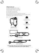
1. Connect the pump to the pipework.
2. Turn on incoming water supply and ensure that all isolating valves are open.
3. Open outlet and check for natural flow from the outlet.
4. Ensure all air is purged from the system.
5. Inspect connections and connecting pipework for leaks.
6. Plug in electrical supply to pump and turn on.
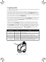
7. The flow will now increase as the pump has entered ‘

Boosting Mode

’.  A  blue  LED         

     will flash on the pump (see Section 7 for location on the pump) to indicate that  

     it is boosting the flow.  
8. Close the outlet fully and the pump will stop. The blue LED remains steady on  

     to indicate it has entered ‘

Standby Mode

’. The pump will remain in  ‘

Standby          

     Mode

’ until the outlet is opened, when it will again begin boosting the flow.

9. When the pump is in ‘

Standby Mode

’ for more than 5 minutes, the blue LED on 

     the pump will turn off until the outlet is opened and the pump begins boosting 

     again.
If TapBoost does not activate, please refer to the troubleshooting section of this 

manual.

8. Commissioning

9. Maintenance

If a drop in performance is noted from TapBoost - the inlet filter 

should be checked and cleaned if necessary. Scan the QR code to 

learn how to clean the filter. Other than the inlet filter, there are 

no user serviceable parts. Any service work involving the repair 

or replacement of parts for the product must be carried out by 

Salamander Pumps, or by one of their approved service engineers.

Note: this includes the pump, power supply unit and all power cords provided.

-  Complies with the Water Supply (Water Fittings) Regulations 1999.

-  IPX4 Rated – Pump

-  IPX0 Rated - Electrical Transformer. Note: must be protected against  


water and moisture

-  UKCA and CE Marked.

-  EN55014-1:2021 Electromechanical compatibility (EMC) – requirements,  


household appliances, electrical goods, and similar apparatus (Part 1).

-  BS EN 60335-1:2012+A15:2021 & BS EN 60335-2-41:2003+A2:2010  


Household and similar electrical appliances – safety (Part 1 General  


requirements & Part 2-41 Particular requirements for pumps).

10. Standards & Approvals

The company operates a policy of continuous development and reserves the 

right to change any of the specifications without prior notice. All information, 

data and illustrations given in this leaflet may be subject to variation.

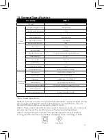
Summary of Contents for TapBoost TBS15

Page 1: ...and warranty guide for TapBoost ISSUE 1 0 March 2022 This document should be given to the end user and retained for future reference Should you need to contact Salamander Pumps you will need the below...

Page 2: ...ons and local byelaws Correct installation is essential for safe operation and a trouble free system It is therefore important to read these instructions thoroughly and ensure you comply with them Inc...

Page 3: ...5 Typical Installations 6 6 Additional Safety Instructions for 8 Bathroom Shower Room Installations 7 Lighting Codes 9 8 Commissioning 10 9 Maintenance 10 10 Standards and Approvals 10 11 General Spec...

Page 4: ...there are no restrictions in the pipework outlet If the natural flow rate is greater than 1 2 lpm TapBoost will increase your outlet flow rate up to a maximum of 11 lpm Refer to Figure 1 below to see...

Page 5: ...factory Some residual water may be present within the pump Important safety information Only the Power Supply Unit and Mains Power Cable provided must be used to operate TapBoost TapBoost Pump with 0...

Page 6: ...so as to stop airflow for ventilation The installation must comply with any local byelaws the Water Supply Water Fittings Regulations 1999 BS EN 806 and in accordance with IET Electrical Regulations G...

Page 7: ...tallation Solder flux should not come into contact with any part of TapBoost the power supply unit or its power cables Never fit to restrictive or collapsed pipework supply e g lead main When installe...

Page 8: ...d in a bathroom shower room please also take note of the additional safety information in Section 6 Single Taps on Sinks Basins Baths Hot and Cold Hot only Cold only Hot and Cold Hot only Cold only Ho...

Page 9: ...TapBoost and all electrics must be inside Toilets Kitchen Appliances Electric Showers Hot and Cold Hot only Cold only Non return valve on cold Non return valve on hot Thermostatic Mixer Showers Outsid...

Page 10: ...cted against moisture and water The plug must be located outside of the bathroom The installation must be carried out to comply with the latest wiring electrical regulations building regulations and l...

Page 11: ...e When an outlet is opened and water begins to flow TapBoost will begin boosting the flow and the LED will fast flash to indicate Boosting Mode If the outlet is closed TapBoost will enter Standby Mode...

Page 12: ...Commissioning 9 Maintenance If a drop in performance is noted from TapBoost the inlet filter should be checked and cleaned if necessary Scan the QR code to learn how to clean the filter Other than the...

Page 13: ...e for activation 1 2 lpm Backflow protection Integrated non return valve Pump inlet connection 15mm compression Pump outlet connection 1 2 male BSP Pump enclosure protection IPX4 Pump weight 0 6 Kg Mo...

Page 14: ...dropping below 11 lpm Air in system Run water through the system with the pump electrically disconnected for several minutes to clear all air Pump operates with all outlets closed Leak in system Chec...

Page 15: ...o year warranty This warranty will operate from the date of purchase and is subject to the installation guidelines being followed correctly Please complete the warranty registration on our website www...

Page 16: ...en replaced by a type not specified by the Company or if the equipment is incorrectly installed operated or used other than as described in the instruction manual or if any servicing or repair of the...

Page 17: ...anty shall be part of the above period s which remain unexpired d In the event of a claim for repairs or replacement being made under the terms of this Warranty a visit from a Salamander service engin...

Page 18: ...16 Notes...

Page 19: ...17 Notes...

Page 20: ...er your warranty Apply online at www salamanderpumps co uk Apply by phone 0191 516 2002 Unit 2c Colima Avenue Enterprise Park West Sunderland SR5 3XE Get in touch we re here to help call us on 0191 51...

Reviews: