Summary of Contents for H1 Series

Page 1: ...H1 Series 0...

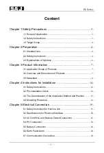
Page 2: ...imensions of Products 7 3 3 Datasheet 8 Chapter 4 Instructions for Installation 14 4 1 Safety Instructions 14 4 2 Pre installation Check 14 4 3 The Determination of the Installation Method and Positio...

Page 3: ...evice 35 Chapter 6 Debugging Instructions 36 6 1 Introduction of Human computer Interface 36 6 2 First Run Setup 37 6 3 Shut Down Inverter 59 6 4 Monitoring Operation and Battery manage system 59 Chap...

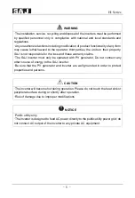
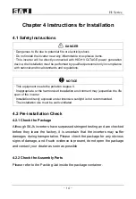
Page 4: ...and maintenance and follow the instruction during installation and operation Please keep this manual all time available in case of emergency 1 2 Safety Instructions DANGER DANGER indicates a hazardou...

Page 5: ...Instructions DANGER There is possibility of dying due to electrical shock and high voltage Do not touch the operating component of the inverter it might result in burning or death To prevent risk of e...

Page 6: ...warranty claims The SAJ inverter must only be operated with PV generator Do not connect any other source of energy to the SAJ inverter Be sure that the PV generator and inverter are well grounded in o...

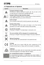
Page 7: ...ing during operating An error has occurred Please go to Chapter 9 Troubleshooting to remedy the error This device SHALL NOT be disposed of in residential waste Please go to Chapter 8 Recycling and Dis...

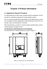
Page 8: ...onverts the DC generated by solar panels into AC which is in accordance with the requirements of public grid and send the AC into the grid reduce the load pressure of the grid When the grid failure pr...

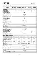
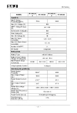
Page 9: ...Data Battery Type Lithium battery Battery Input Voltage Range of Voltage V 48 42 58 4 Max Rated Charge Current A 60 60 100 100 Charging Mode Control 3 stages Grid Data On grid Mode Rated Output Power...

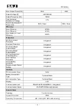
Page 10: ...ltage Protection Integrated AC Overvoltage Undervoltage Protection Integrated AC Overfrequency Underfrequency High Low Protection Integrated Over Thermal Protection Integrated Anti islanding protectio...

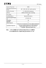
Page 11: ...g Noise dBA 29 Cooling method Natural Convection Dimensions H W D m m 470 470 190 Weight kg 23 Standard Warranty year 5 Applicable Standard IEC62109 1 2 IEC61000 6 1 2 3 4 EN50438 EN50549 C10 C11 IEC...

Page 12: ...tch Integrated Battery Data Battery Type Lithium battery Battery Input Voltage Range of Voltage V 48 42 58 4 Max Rated Charge Current A 60 60 100 100 60 60 100 100 Charging Mode Control 3 stages Grid...

Page 13: ...rotection Integrated Overload Protection Integrated DC Overvoltage Undervoltage Protection Integrated AC Overvoltage Undervoltage Protection Integrated AC Overfrequency Underfrequency High Low Protect...

Page 14: ...ooling method Natural Convection Dimensions H W D m m 470 470 190 Weight kg 23 Standard Warranty year 5 Applicable Standard IEC62109 1 2 IEC61000 6 1 2 3 4 EN50438 EN5054 9 C10 C11 IEC62116 IEC61727 R...

Page 15: ...or the harmonized installation environment may jeopardize the life span of the inverter Installation directly exposed under intensive sunlight is not recommended The installation site must be well ven...

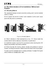
Page 16: ...ethod 2 Mount vertically or tilted backwards by max 15 Never install the inverter tilted forwards sideways horizontally or upside down 3 Install the inverter at eye level for convenience when checking...

Page 17: ...30CM Figure 4 2 Minimum Clearance 4 4 Mounting Procedure 4 4 1 Mark the Positions of the Drill Holes of the Rear Panel The mounting position should be marked as shown in Figure 4 3 Figure 4 3 Dimensi...

Page 18: ...with position marked in Figure 4 4 and then place expansion tubes in the holes using a rubber mallet Figure 4 4 Drill holes dimensions of H1 inverter 4 4 3 Mount the Screws and the Rear Panel The pan...

Page 19: ...18 4 4 4 Mount the Inverter Carefully mount the inverter to the rear panel as shown in Figure 4 6 Make sure that the rear part of the equipment is closely mounted to the rear panel Figure 4 6 Mount H1...

Page 20: ...lectricity shock When power on the equipment should in conformity with national rules and regulations The direct connection between the inverter and high voltage power systems must be operated by qual...

Page 21: ...rface Figure 5 1 Electrical Interface of H1 inverter Table 5 1 Specifications for Interface Code Name A Battery Input B RS232 4G GPRS Wi Fi Port C RS485 DRM Port CAN D DC Input E DC Switch F On Grid T...

Page 22: ...able Cross sectional area mm External diameter mm Range Recommend Range Recommend 2 5 6 0 4 0 8 14 14 Table 5 2 Recommended Specifications of AC Cables If the grid connection distance is too far pleas...

Page 23: ...Series 22 5 3 2 Connect the cables according to connection marks of L N and PE Figure 5 3 Connect the Cables 5 3 3 Secure all parts of the grid and backup connector tightly Figure 5 4 Screw the Connec...

Page 24: ...6 0 4 0 4 2 5 3 5 3 Table5 3 Recommended Specifications of DC Cables DC connector is made up of the positive connector and the negative connector 1 Insulated Enclosure 2 Lock Screw 3 Positive Connecto...

Page 25: ...terminals into positive cable and negative cable whose insulated enclosure has been stripped off and crimp them tightly with a wire crimper Make sure that the withdrawal force of the pressed cable is...

Page 26: ...tion Port Figure 5 8 Connect the Inverter NOTICE Before insert the connector into DC input terminal of the inverter please make sure that the DC switch of the inverter is OFF Please use the original H...

Page 27: ...um battery is preferred as it is capable of direct communication to the charging devices SAJ shall not be responsible for the battery safety and performance or services provided by battery supplier Ca...

Page 28: ...feed the battery cable through the AC waterproof hole Figure5 9 Open the waterproof cover Strip off the insulation skin of DC cable the core is exposed to 10mm and use a special tool to press the Bat...

Page 29: ...Battery Cable 5 6 Earth Fault Alarm This inverter complies with IEC 62109 2 clause 13 9 for earth fault alarm monitoring If an Earth Fault Alarm occurs the second LED indicator will be lit up and err...

Page 30: ...Number Description Effect 1 7V Power supply 2 RS 232 TX Send data 3 RS 232 RX Receive data 4 GND Ground wire Table 5 5 9 Pin serial port introduction USB interface with Wi Fi module please reference...

Page 31: ...ies 30 Left 1 DRM 1 5 DRM 2 DRM 2 6 3 DRM 3 7 4 DRM 4 8 5 RefGen 6 Com DRM 0 7 V 8 V Right CAN 1 NC 2 NC 3 NC 4 CANH 5 CANL 6 NC 7 NC 8 NC Table 5 6 RJ45 pin port definition Figure 5 13 Interface defi...

Page 32: ...or further details for the smart meters If users have no intention to set the export limitation function please ignore chapter 5 7 4 If users have purchased the smart meter that recommended by SAJ bef...

Page 33: ...meter and check if the meter is running 5 Confirm communication address of meter and hybrid inverter For both meter and hybrid inverter the default communication address is 1 If the communication add...

Page 34: ...the interface of choosing Export Limitation Setup as shown below Figure 5 17 Mode Setting Note Meter is not waterproof or dust proof it is recommended to install it in the distribution box If the cur...

Page 35: ...H1 Series 34 5 8 Connection Diagram Figure 5 18 H1 Connection diagram...

Page 36: ...uit breaker to ensure the inverter is able to disconnect from grid safely The inverter is integrated with a RCMU however an external RCD is needed to protect the system from tripping either type A or...

Page 37: ...ntroduction of Human computer Interface A B C D E F G Figure 6 1 Human computer Interface LED indicator Function A Power status On Green LED on Off LED off B Run fault status Inverter running properly...

Page 38: ...seconds Return to main menu or canceling the setting Press time longer than 2 seconds Cut off output to load G ENT Press time shorter than 2 seconds Enter the sub menu or confirming a selection Press...

Page 39: ...tching to next parameter setting by pressing ENT Drop out of edit by pressing ESC Operating and interface description Set the date and time according to the MM DD YYYY and hh mm ss format Note If user...

Page 40: ...y Ah DisCharge Depth Pb Li 100 20 Ok Figure 6 4 Battery setting 6 2 4 Set the Country When the inverter begins to run for the first time please configure the country of usage each country is integrate...

Page 41: ...f users cannot find out the corresponding country please stop the setting and contact the after sales for confirmation 6 2 5 Inverter System Main Interface After the country has been set system will r...

Page 42: ...power the PV dynamic power flow arrow will disappear When no load output the load output dynamic power flow arrow will disappear In system main screen user could press or to view different charts PV...

Page 43: ...daily power generation Day PV Energy 2019 08 14 18 26 31 0 3 6 9 12 15 18 21 24 Day kWh 1 0 2 0 3 0 4 0 5 0 6 0 7 0 8 0 9 0 10 0 27 30 E Month 0 00kWh PV Figure 6 14 Daily generation in this month In...

Page 44: ...26 31 0 3 6 9 12 15 18 21 24 Day kWh 1 0 2 0 3 0 4 0 5 0 6 0 7 0 8 0 9 0 10 0 27 30 E Month 0 00kWh Load Figure 6 17 Daily load consumption in this month In the figure above it shows the daily output...

Page 45: ...E Total 4 46kWh Figure 6 19 Totally PV Trading power and load consumption In the figure above it shows the annual power of PV Grid trading power and load output in recent 6 years It also shows the fin...

Page 46: ...ext interface 2019 08 14 18 26 31 Graph Setting Run Info About Figure 6 22 Main edit interface If the menu option has a secondary menu interface it will appear by press the ENT button The figure below...

Page 47: ...f About Device Type XXXX Device SN Code 32030G1547CN02000 Device PC Code SF05KMTL1CN6ED1000 HMI SW V2 001 Master Ctrl SW V1 007 Slaver Ctrl SW V1 007 Grid Country Australia Grid Compliance AS4777 2019...

Page 48: ...Info About App Mode Smart Home Mode Inverter State Standby State Temperature 36 5 BUS Voltage 384 2V Charge State Disable DisCharge State Disable OutPut State Disable Sell Execess Energy Disable Ambt...

Page 49: ...6 31 Battery Type Lead acid Battery Battery Current 1 01A Total Capacity 100Ah Battery Voltage 50 5V Battery Power 51W Figure 6 31 Information of Lead acid battery In main edit interface by selecting...

Page 50: ...menu press ENT to enter the secondary menu then select Mode Setting press ENT to enter the interface of choosing running mode as shown below 2019 08 14 18 26 31 Graph Setting Run Info About User Mode...

Page 51: ...ing period and discharging period can be set during charging period battery can only be charged while in discharging period battery can only be discharged the rest of the period battery will behave as...

Page 52: ...se working date press ENT to select or cancel press ESC to return to previous interface as shown below 2019 09 16 18 26 31 Graph Setting Run Info About Monday Tuesday Wednesday Thursday Friday Saturda...

Page 53: ...N RS485 100 45 0 54 5 Ah V V OK Total Capcity 20 Figure 6 40 Interface of battery parameter setup General setting Select Setting in menu press ENT button to enter the secondary menu select System Sett...

Page 54: ...tup 2019 08 14 18 26 31 Graph Setting Run Info About 08 14 2019 18 32 06 Date Time Set System Time And Date Ok Figure 6 43 System date and time setup 2019 09 16 18 26 31 Graph Setting Run Info About L...

Page 55: ...ing Ok Figure 6 45 Factory setting 2019 08 15 18 26 31 Graph Setting Run Info About Attention If you click the button OK All the generated energy data such as E today E month E year E total saved in t...

Page 56: ...ng Run Info About 1 rs232 address rs232 bandurate 115200 1 rs485 address rs485 bandurate 9600 bit s bit s Ok Figure 6 49 Communication set 2019 08 15 18 26 31 Graph Setting Run Info About Please enter...

Page 57: ...the information about the error or warning The status light will turn red as well Energy Direction 2019 09 16 18 26 31 65 Lost Com H M Err Error Infor Ok Figure 6 52 Interface of error or warning The...

Page 58: ...o confirm inverter begins to enter loading status As shown below Energy Direction 2019 09 16 18 26 31 1200W 500W 2000W 50 8V InPut Load Message Info Ok 1200W 500W 2000W 50 8V InPut Load Message Info O...

Page 59: ...H1 Series 58 Energy Direction 2019 09 16 18 26 31 1200W 500W 2000W 50 8V Cutoff Load Message Info Ok Figure 6 56 Process of cutoff load...

Page 60: ...equipped with a RS232 interface RS232 can connect with Wi Fi module which can be used in monitoring of the operation status By connecting the internet through a Wi Fi module and uploading the data of...

Page 61: ...12 DCI Err DCI Devices Error Error 13 HWBus Volt High Err Bus Hardware Over voltage Error 14 HWPV1 Curr High Err PV1 Hardware Over current Error 15 HWPV2 Curr High Err PV2 Hardware Over current Error...

Page 62: ...utput Connection error Error 43 Inv Wave Err Inverter voltage wave error Error 44 GFCI Consis Err Data Consistency of GFCI Error Error 46 DVI Consis Err Data Consistency of DVI Error 47 CHG1 Curr Err...

Page 63: ...rror 68 BMS Device Err BMS Device Error Error 81 BMS Cell Volt H Warn BMS cell voltage high warning Alarm 82 BMS Cell Volt L Warn BMS cell voltage low warning Alarm 83 BMS CHG Curr H Warn BMS charging...

Page 64: ...This device should not be disposed as residential waste An Inverter that has reached the end of its life and is not required to be returned to your dealer it must be disposed carefully by an approved...

Page 65: ...uangdong P R China Postcode 510663 Web http www saj electric com Technical Support Service Tel 86 20 6660 8588 Fax 86 20 6660 8589 E mail service saj electric com International Sales Tel 86 20 6660861...

Page 66: ...please complete the below forms and send this page to SAJ attached with the Customer s invoice For Customer to fill in Name City Country Zip Tel Fax E mail Information on Device Device type Serial No...

Page 67: ...H1 Series 66 For Installer to fill in Modules Used Modules Per String No of String Installation Company Contractor License Number Company City Country Zip Tel Fax E mail Signature Date...

Page 68: ...H1 Series 67...
Reviews: