


81
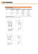
Only pins 4 and 5 on the RJ45 plug should be wired. The other pins on the HPVFE RJ45 socket contain power, etc.
for other Solcom&Hapn peripheral devices and must not be connected.
Wiring terminations on the master controller will vary depending on the master controller used and “TxRxD+” and
“TxRxD-” are shown for illustration purposes only. Refer to the master controller’s user manual for network
terminations. Note that there is no standard for the “+” and “-” wires, and consequently Modbus device
manufacturers interpret them differently. If you have problems with initially establishing communications, try
swapping the two network wires at the master controller.
Standard RS485 wiring practices apply.
Termination resistors need to be applied at each end of the network cable.
•
RS485 repeaters may need to be used for long cable runs, or if greater than 32 nodes are needed on the network.
Network wiring should be separated from power wires by at least 0.3 meters (1 foot).
Network wiring should only cross power wires at a right angle.
Control Terminal 16 on the HPVFE must also be connected to PE ground (there are two PE terminals on the drive).
See
Figure 1.5
for more information.
Network Common is internally tied to I/O Terminal 04 (Digital Common). Tying I/O Terminal 04 to PE ground
may improve noise immunity in some applications.
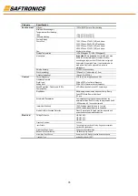
Parameter Configuration
The following HPVFE parameters are used to configure the drive to operate on a network.
Parameter
Details
Reference
P106
[Start Source]
Set to
5 “RS485 (DSI) Port” if Start is controlled from the network.
Page 3-9
P108
[Speed Reference]
Set to 5
“RS485 (DSI) Port” if the Speed Reference is controlled from the network.
Page 3-11
C302
[Comm Data Rate]
Sets the data rate for the RS485 (DSI) Port. All nodes on the network must be set to the
same data rate.
Page 3-17
C303
[Comm Node Addr]
Sets the node address for the drive on the network. Each device on the network requires a
unique node address.
Page 3-17
C304
[Comm Loss Action]
Selects the drive’s response to communication problems.
Page 3-17
C305
[Comm Loss Time]
Sets the time that the drive will remain in communication loss before the drive implements
A105 [Comm Loss Action].
Page 3-18
C306
[Comm Format]
Sets the transmission mode, data bits, parity and stop bits for the RS485 (DSI) Port. All
nodes on the network must be set to the same setting.
Page 3-18
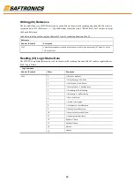
Supported Modbus Function Codes
The peripheral interface (DSI) used on HPVFE drives supports some of the Modbus function codes.
Modbus Function Code (Decimal)
Command
03
Read Holding Registers
06
Preset (Write) Single Register
16 (10 Hexadecimal)
Preset (Write) Multiple Registers
Important:
Modbus devices can be 0-based (registers are numbered starting at 0) or 1-based (registers are
numbered starting at 1). Depending on the Modbus Master used, the register addresses listed on the following
pages may need to be offset by +1. For example, Logic Command may be register address 8192 for some master
devices (e.g. ProSoft 3150-MCM SLC Modbus scanner) and 8193 for others (e.g. PanelViews).