


Terminal Block Group
(continued)
47
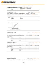
Analog inversion can be accomplished by setting this value smaller than
t213
[Anlg In4-20mA Lo] or by setting
t201 - t202
[Digital Inx Sel] to
option 15 “Anlg Invert”
Values
Default
100.0%
Min/Max:
0.0/ 100.0%
Display:
0.1%
t221 [Relay Out Sel]
Related Parameter(s
): P103, t222, A451
Sets the condition that changes the state of the output relay contacts.
Options
0
“Ready/Fault”
(Default)
Relay changes state when power is applied. This indicates that the drive is ready
for operation. Relay returns drive to shelf state when power is removed or a fault
occurs.
1
“At Frequency”
Drive reaches commanded frequency.
2
“MotorRunning”
Motor is receiving power from the drive.
3
“Reverse”
Drive is commanded to run in reverse direction.
4
“Motor Overld”
Motor overload condition exists.
5
“Ramp Reg”
Ramp regulator is modifying the programmed accel/decel times to avoid an
overcurrent or overvoltage fault from occurring.
6
“Above Freq”
Drive exceeds the frequency (Hz) value set in
t222
[Relay Out Level].
7
“Above Cur”
Drive exceeds the current (% Amps) value set in
t222
[Relay Out Level].
Important:
Value for
t222
[Relay Out Level] must be entered in percent of drive
rated output current.
8
“Above DCVolt”
Drive exceeds the DC bus voltage value set in
t222
[Relay Out Level].
9
“Retries Exst”
Value set in
A451
[Auto Rstrt Tries] is exceeded.
10
“Above Anlg V”
Analog input voltage (I/O Terminal 13) exceeds the value set in
t222
[Relay Out
Level].
This parameter setting can also be used to indicate a PTC trip point when the
input (I/O Terminal 13) is wired to a PTC and external resistor.
Use
t222
to set threshold.
11
“ParamControl”
Enables the output to be controlled over network communications by writing to
t222
[Relay Out Level].
(0 = Off, 1 = On.)
12
“NonRec Fault””
Value set in
A451
[Auto Rstrt Tries] is exceeded.
A451
[Auto Rstrt Tries] is not enabled.
A Non-resettable fault has occurred.
13
“I/O Control”
Enables the output to be controlled by bit 6 of the logic command word. See
Writing (06) Logic Command Data on page C-4
for more information.
14-22
Reserved