


Sailer Manual HPVFE
27
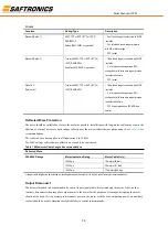
EN61000-3-2
•0.75 kW (1 HP) 240V 1-Phase and3-Phase drives and
0.4 kW (0.5 HP) 240V 1-Phase drives are suitable for installation on a private low voltage power network.
Installations on a public low voltage power network may require additional external harmonic mitigation.
•Other drive ratings meet the current harmonic requirements ofEN61000-3-2 without additional external
mitigation.
Chapter2 Start Up
This chapter describes how to start up the HPVFE Drive. To simplify drive setup, the most commonly
programmed parameters are organized in a single Basic Program Group.
Important:
Read the
General Precautions
section before proceeding
.
ATTENTION:
Power must be applied to the drive to perform the following start-up procedures.Some
of the voltages present are at incoming line potential. To avoid electric shock hazard or damage
to equipment, only qualified service personnel should perform the following procedure. Thoroughly
read and understand the procedure before beginning. If an event does not occur
While performing this procedure,
Do Not Proceed
.
Remove All Power
including user supplied
control voltages. User supplied voltages may exist even when main AC power is not applied to the
drive. Correct the malfunction before continuing.
Prepare For Drive Start-Up
Before Applying Power to the Drive
❏
1.
Confirm that all inputs are connected to the correct terminals and are secure.
❏
2.
Verify that AC line power at the disconnect device is within the rated value of the drive.
❏
3.
Verify that any digital control power is 24 volts.
❏
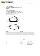
4.
Verify that the Sink (SNK)/Source (SRC) Setup DIP Switch is set to match your control wiring scheme. See
Figure 1.5 on page 1-14
for location.
Important:
The default control scheme is Source (SRC). The Stop terminal is jumpered (I/O Terminals 01 and 11)
to allow starting from the keypad. If the control scheme is changed to Sink (SNK), the jumper must be removed
from I/O Terminals 01 and 11 and installed between I/O Terminals 01 and 04.
❏
5.
Verify that the Stop input is present or the drive will not start.
Important:
If I/O Terminal 01 is used as a stop input, the jumper between I/O Terminals 01 and 11 must be
removed.