background image

MorphoWave

TM


OEM

 Installation Guide 


Annex 1 :  Maintenance 


2015_2000009096 V4 
May 2017 

This document and the information therein are the property of Morpho. 
They must not be copied or communicated to a third party without the prior written authorization of Morpho


87 


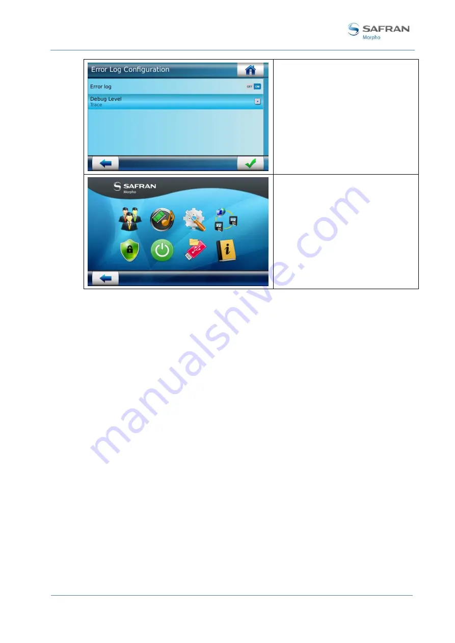
Select ON for Error log button. 

Select in Debug Level menu the Trace 
level. 


Validate  your  choice  and  in  the 
administration  menu  select  reboot 
button.  A  reboot  is  required  to 
activate all logs. 


Logs retrieval on MorphoAccess Sigma Wave and PC: 

-


To  retrieve  logs  on  MorphoAccess  Sigma  Wave,  please  use 
MorphoBioToolBox software. 

-


To  retrieve  logs  on  PC,  log  in  windows  and  then  go  in  C:\Program  Files 
(x86)\Morpho\FOTF\FOTF Server\Logs. 

-


Send to Morpho all files contained in this folded to ensure debug and a quick 
solution. 


Summary of Contents for Morpho MorphoWave OEM

Page 1: ...COPYRIGHT 2016 Morpho Osny France MorphoWave OEM Installation Guide May 2017 2015_2000009096 V4 MorphoWave OEM Installation Guide...

Page 2: ...served Information in this document is subject to change without notice and do not represent a commitment on the part of Morpho No part of this document may be reproduced or transmitted in any form or...

Page 3: ...ho 3 Revision History The table below contains the history of changes made to the present document Version Date Reference Description 01 July 2015 2015_2000009096 V1 Document creation 02 December 2015...

Page 4: ...mation 11 Canada information 12 UL information 12 Recommendations for terminal implementation 14 Section 2 General Description 17 MorphoWaveTM OEM Overview 18 MorphoAccess Sigma Wave box opening 19 Co...

Page 5: ...4 First biometric record and identification 55 Default passwords to be changed 59 First connection to an external network 60 Modes for controlling access rights 61 Introduction 61 Identification mode...

Page 6: ...Wave connection for maintenance 88 MorphoAccess Sigma PC internal connection checking 92 How to get the latest versions of documents 94 Documents concerning the MorphoWave OEM terminal 95 Documents a...

Page 7: ...re 8 Drilling template 33 Figure 9 Wall plate preparation for water tightness 34 Figure 10 Wall plate fixing 34 Figure 11 Cabling preparation 35 Figure 12 Ground wiring 36 Figure 13 Cabling layout 37...

Page 8: ...1 Introduction 8 This document and the information therein are the property of Morpho They must not be copied or communicated to a third party without the prior written authorization of Morpho 2015_20...

Page 9: ...eTM OEM integrates Morpho image processing and feature matching algorithms This technology is based on lessons learned during 25 years of experience in the field of biometric identification and the cr...

Page 10: ...2 requirements or supplied by a listed IEC60950 1 external Power Unit marked Class 2 Limited Power source or LPS and rated 12VDC 1A minimum or 24VDC 0 5A minimum In case of building to building connec...

Page 11: ...Morpho hereby declares that products delivered MorphoAcces Sigma MorphoWave Desktop with the MorphoWaveTM OEM bundle have been tested and found compliant with following listed standards EMC Directive...

Page 12: ...aler or an experienced radio TV technician for help Shielded cables must be used with this unit to ensure compliance with category B FCC restrictions Canada information WARNING TO USERS IN THE CANADA...

Page 13: ...ut was verified RS422 RS485 Wiegand and Ethernet communication were verified with a supplemental computer employing the vendor s proprietary software MBTB UL version 2 0 4 0 Please note that the follo...

Page 14: ...ired decide if a network is required and decide on the location and number of required terminals Unpack all items Unpack all items and check against the packing list Install network hardware component...

Page 15: ...omprises The MorphoWaveTM OEM terminal itself Its role is to perform one to many biometric identification or one to one biometric verification i e to identify the individual who is presenting his hand...

Page 16: ...th anti pulling and anti tamper switches for more explanations The Controller is part of the global Access Control System of the secured area which for instance can administrate the White List of the...

Page 17: ...al Description 2015_2000009096 V4 May 2017 This document and the information therein are the property of Morpho They must not be copied or communicated to a third party without the prior written autho...

Page 18: ...orphoWaveTM OEM Overview The MorphoWaveTM OEM is a bundle of Morpho products enabling any integrator to build easily an access control solution with contactless fingerprints sensor the MorphoWave Desk...

Page 19: ...oAccess Sigma Wave components shall be extracted from the protection casing as depicted in the pictures below Extract the wall plate which is not screwed to the terminal and keep it separate until the...

Page 20: ...the property of Morpho They must not be copied or communicated to a third party without the prior written authorization of Morpho 2015_2000009096 V4 May 2017 Terminal s front view description Figure 4...

Page 21: ...icated to a third party without the prior written authorization of Morpho 21 Terminal s rear view description Figure 5 MorphoAccess Sigma Wave terminal rear view Battery installation in front of user...

Page 22: ...top It is 4 fingers contactless sensor NB You may receive a MorphoAccess Sigma Wave still equipped with a slap sensor built in In a MorphoWave OEM context this sensor is disabled False Acceptance Rate...

Page 23: ...on one relay switch open in default state Size and weight W x H x D 150 5mm x 152 5mm x 57 5mm 5 92 x 6 00 x 2 26 Weight 580g Environmental conditions Operating temperature 10 C to 55 C 14 F to 131 F...

Page 24: ...orphoWaveTM Desktop box opening MorphoWaveTM Desktop or previously called Finger On The Fly is a biometric sensor providing an innovative and effective solution for performing very fast acquisitions o...

Page 25: ...cluding external power supply Interface Host PC Connectivity USB 3 0 Environmental Conditions Capture Volume W x H x D 40mm x 39mm x 80mm 1 57in x 1 53in x 3 14in Operating Temperature 0 C 32 F to 43...

Page 26: ...of Morpho They must not be copied or communicated to a third party without the prior written authorization of Morpho 2015_2000009096 V4 May 2017 The external power supply of MorphoWave Desktop is prov...

Page 27: ...led with Morpho software This configuration is powered with a high end Intel i7 processor to ensure optimal performances for access control application The PC is delivered as a ready to plug component...

Page 28: ...Switch Wave provided with MorphoWaveTM OEM has a specific configuration inside loaded by Morpho facility This configuration will ensure an isolated and secured communication between MorphoAccess Sigm...

Page 29: ...tion Procedure 2015_2000009096 V4 May 2017 This document and the information therein are the property of Morpho They must not be copied or communicated to a third party without the prior written autho...

Page 30: ...ponents described in Components of the initial package section at your disposal Remove the wall plate Keep this element at hand Remove the screw at the bottom of the product Keep this element at hand...

Page 31: ...ve One 1 hole saw 67mm depending on installation case One 1 Flat tip screwdriver 0 4x2 0 for block connector cable removal A 1 Torx T10 screwdriver Deadbolt door strike Snubber diode required to prote...

Page 32: ...mera height For an optimal use the terminal must be installed in an area where the lighting conditions are controlled Avoid direct exposure of the sensor to the sun light and ensure good ambient light...

Page 33: ...Drilling the mounting holes Figure 8 Drilling template If not present drill in the wall a hole with a diameter of 67mm see Figure 8 Drilling template This template can be found in the Quick Installat...

Page 34: ...Figure 9 Wall plate preparation for water tightness Create a silicone bead all along the notch The silicone bead shall be reduced to avoid overflow on the upper part of the wall plate risk to prevent...

Page 35: ...m stripped on 0 6mm Figure 11 Cabling preparation Prefer rigid cable to flexible cable easier to connect Connection details Characteristics min max Conductor cross section solid or stranded 0 2 mm 0 5...

Page 36: ...harge of installation and connections is properly connected to earth in order to prevent Electrostatic Discharges ESD In case of more than two digital signals use digital grounds shall all be wired to...

Page 37: ...o 37 Figure 13 Cabling layout To connect wire to block connector insert cable in the round hole of the connector To remove wire insert a flat screw driver 0 4x2 0max in the rectangular hole of the con...

Page 38: ...May 2017 External Power supply Figure 14 Power supply wiring A 1 Power Supply 12V In Positive 12 Volts power supply 2 Power ground In Ground power supply External power supply Must comply with CEE IE...

Page 39: ...f Morpho 39 POE Power Over Ethernet MorphoAccess Sigma terminal s power supply can also be provided by the Ethernet using RJ45 connection Power Over Ethernet mode IEEE802 3af compliant This mode is on...

Page 40: ...rip Nominal characteristics of relay Load characteristics 2 A max 30 VDC according to the safety extra low voltage requirements independently of the power supply Resistive load or inductive load see w...

Page 41: ...e for the switch Product installed on the wall plate switch enabled contact closed Product opened rear connectors accessible switch disabled contact open Nominal characteristics of switch block 100 mA...

Page 42: ...n the MorphoAccess Sigma Wave executes all actions configured in case of tamper Wiegand input wiring Figure 19 Wiegand input wiring A 5 Digital ground Ground for Wiegand connect pin 5 or 6 6 Digital g...

Page 43: ...low The controller supports neither LED1 nor LED2 signals When the access controller has no relay contact to provide an answer to the MorphoAccess Sigma Wave terminal then the decision to emit either...

Page 44: ...ranted contact must be connected between the LED1 and the GND wires of the terminal The access denied contact must be connected between the LED2 and the GND wires of the terminal The MorphoAccess Sigm...

Page 45: ...d or communicated to a third party without the prior written authorization of Morpho 45 B 1 D0_IN In Data Output type required Open drain or 5V 5 2 D1_IN In Clock Output type required Open drain or 5V...

Page 46: ...nect pin 5 or 6 B 3 D0_OUT Out Data 5V TTL 4 D1_OUT Out Clock 5V TTL RS485 Figure 23 Serial port wiring RS485 A 5 Digital ground Ground connect pin 5 or 6 6 Digital ground Ground connect pin 5 or 6 D...

Page 47: ...n RS422 inverting Receive 4 RS422 RX In RS422 non inverting Receive 5 RS422TX Out RS422 non inverting Transmit 6 RS422TX Out RS422 inverting Transmit RS422 interface is a full duplex communication GPI...

Page 48: ...used to power the MorphoAccess Sigma Wave terminal through POE Power Over Ethernet IEEE802 3af mode According to the POE standard two modes are available power on data pins and power on dedicated pin...

Page 49: ...ter the administrator may need to modify the network parameters of the Host PC Please refer to following example to connect terminal which is having default network parameter Figure 27 Direct Point to...

Page 50: ...n White green White green White green White green White green White green White green Corel L120 Colors Grey White Pink Orange Yellow Blue Purple Brown Figure 28 RJ45 wiring RJ45 plug pinout is compli...

Page 51: ...esktop installation Prior components wiring the MorphoWaveTM Desktop has to be prepared as following To access the power supply and USB cable remove the rear plastic cover with an M3 CHC screwdriver U...

Page 52: ...or Power Over Ethernet for MorphoAccess Sigma Installation procedure Components wiring requires to not connect power supply of devices during this operation Connect on the PC the biometric sensor on...

Page 53: ...y must not be copied or communicated to a third party without the prior written authorization of Morpho 53 Connect the power adaptor of the MorphoWaveTM Desktop Connect the power adaptor of the Ethern...

Page 54: ...n 4 First boot 54 This document and the information therein are the property of Morpho They must not be copied or communicated to a third party without the prior written authorization of Morpho 2015_2...

Page 55: ...n the MorphoWaveTM OEM PC biometric sensor Ethernet switch For this first training it is not required to plug external network RJ45 cable all operation are suitable for standalone mode The MorphoAcces...

Page 56: ...ust not be copied or communicated to a third party without the prior written authorization of Morpho 2015_2000009096 V4 May 2017 Click on users icons add user Enter user s informations then click on c...

Page 57: ...Follow guidelines displayed on the screen two waves are required to perform one successful record Once the enrollment is successful following screen will be displayed Click on green cross bottom righ...

Page 58: ...third party without the prior written authorization of Morpho 2015_2000009096 V4 May 2017 Click on the green cross bottom right to save the user in local database Then go back in the main menu Click o...

Page 59: ...s default password equal to 12345 The PC Wave password has default password equal to 12345 Please set your own secrets passwords on both devices to ensure privacy on data and MorphoWave management on...

Page 60: ...arty without the prior written authorization of Morpho 2015_2000009096 V4 May 2017 First connection to an external network Prior to connect the MorphoWaveTM OEM on the external network by following Mo...

Page 61: ...can request the access on the terminal This biometric data is acquired either directly on the terminal using the embedded or on an enrolment system using the same type of biometric sensor The access c...

Page 62: ...For further details about SSL or TLS on the MorphoWaveTM OEM terminal please refer to the MorphoWave OEM Series Administration Guide and the MorphoWave addendum External database mode also called poll...

Page 63: ...zation of Morpho 63 MorphoWaveTM OEM terminal also has distant commands to retrieve polling buffer status and polling buffer data How to Activate External database mode can be activated through Webser...

Page 64: ...rphoWaveTM Desktop biometric sensor MorphoWaveTM OEM native mode MorphoWaveTM OEM terminal is by default in native mode that is named MA5G It will support the new features and configurations only in t...

Page 65: ...ugh e g when the terminal is pulled out of the wall When the switches are deactivated the MorphoAccess Sigma Wave terminal acts as required by the related configuration key see MorphoWave OEM Administ...

Page 66: ...C Applications 66 This document and the information therein are the property of Morpho They must not be copied or communicated to a third party without the prior written authorization of Morpho 2015_2...

Page 67: ...Power supply units Power Over Ethernet module enabling POE capabilities on the product User database size licenses MA_10K_USERS MA_40K_USERS enabling database size upgrade from 3 000 to 10 000 40 000...

Page 68: ...ion therein are the property of Morpho They must not be copied or communicated to a third party without the prior written authorization of Morpho 2015_2000009096 V4 May 2017 Compatible PC applications...

Page 69: ...ecommendations 2015_2000009096 V4 May 2017 This document and the information therein are the property of Morpho They must not be copied or communicated to a third party without the prior written autho...

Page 70: ...ided in areas where the terminal has been installed Areas containing combustibles It is strongly recommended that you do not install your terminal in the vicinity of gas stations petroleum processing...

Page 71: ...r Clean the glass every day to optimize performances of the product especially when there is heavy dust deposit on the capture window Use a dry cloth to clean the terminal and the sensor The use of ac...

Page 72: ...opied or communicated to a third party without the prior written authorization of Morpho 2015_2000009096 V4 May 2017 GPI GPO MA SIGMA family GPI 3 GPI GPO 3 GPO 3 TTLOUT_H only GPO current limitation...

Page 73: ...r switches MA SIGMA family Anti theft switch Yes Tamper switch Yes Warning to a host if the product isn t supplied Yes Micro SD card The micro SD card is provided to ensure database storage Lighting c...

Page 74: ...a biometric acquisition terminal which captures fingerprints by the applicant waving their hand through the active volume The product can track and capture simultaneously up to 4 fingerprints at a max...

Page 75: ...orpho 75 Capture Recommendations Proper Use Below are several illustrations and guidelines on how to best use your new MorphoWaveTM Desktop device 1 Insert your hand flat palm down from the front of t...

Page 76: ...of Morpho 2015_2000009096 V4 May 2017 Improper Use The following illustrations show what NOT to do when using MorphoWave Desktop 1 Do not place your hand upside down 1 Do not cross your fingers 2 Do...

Page 77: ...communicated to a third party without the prior written authorization of Morpho 77 8 Do not place your hand on the edge of the optical sensor 9 Do not place your hand too far up on the optical sensor...

Page 78: ...e Section 6 Recommendations 78 This document and the information therein are the property of Morpho They must not be copied or communicated to a third party without the prior written authorization of...

Page 79: ...1 Maintenance 2015_2000009096 V4 May 2017 This document and the information therein are the property of Morpho They must not be copied or communicated to a third party without the prior written autho...

Page 80: ...et the Ethernet switch disconnected from customer network The goal is to isolate the MorphoWaveTM OEM from the customer network at the first boot so as to avoid any conflicts due to of the IT architec...

Page 81: ...uide Annex 1 Maintenance 2015_2000009096 V4 May 2017 This document and the information therein are the property of Morpho They must not be copied or communicated to a third party without the prior wri...

Page 82: ...useful when a couple of MorphoAccess Sigma Wave and PC Wave are changed by new devices This unpairing procedure explain you how to disassociate a couple of device Procedure 1 Unconnect the RJ45 cable...

Page 83: ...sor Then confirm At this point of time the MorphoAccess Sigma Wave has forgotten the PC connected NB When a unpaired PC running MorphoWave software will be connected to the MorphoAcce Sigma Wave a new...

Page 84: ...n database PC Wave change procedure To replace the PC on MorphoWaveTM OEM system On the MorphoAccess Sigma Wave follow the unpairing procedure step 1 and 2 to disassociate the sensor Turn off the enti...

Page 85: ...ure To replace the Ethernet switch Turn off the entire system MorphoAccess Sigma Wave MorphoWaveTM Desktop PC Ethernet switch Unplug the Ethernet switch and replace it by the new one Please take care...

Page 86: ...ion of Morpho 2015_2000009096 V4 May 2017 Debug logs activation On Morpho request and to solve issue it might be required to activate debug logs level for further investigation Please follow instructi...

Page 87: ...g button Select in Debug Level menu the Trace level Validate your choice and in the administration menu select reboot button A reboot is required to activate all logs Logs retrieval on MorphoAccess Si...

Page 88: ...onnect manually on the PC Wave of the MorphoWaveTM OEM There are two solutions to connect to the PC Wave of the MorphoWaveTM OEM To connect VGA cable keypad and mouse To establish a Windows remote ses...

Page 89: ...ment and the information therein are the property of Morpho They must not be copied or communicated to a third party without the prior written authorization of Morpho 89 In local area connection statu...

Page 90: ...f the laptop may require deactivation then reactivation to apply new settings In such case use the device manager control panel of windows and right click on the Ethernet chipset to activate and disab...

Page 91: ...erein are the property of Morpho They must not be copied or communicated to a third party without the prior written authorization of Morpho 91 After maintenance operation On the laptop it is recommend...

Page 92: ...oth devices Please follow instructions below Apply Remote PC Wave connection for maintenance procedure to be connected on PC Launch console application and type ping 169 254 169 101 If the ping is not...

Page 93: ...2 Bibliography 2015_2000009096 V4 May 2017 This document and the information therein are the property of Morpho They must not be copied or communicated to a third party without the prior written autho...

Page 94: ...third party without the prior written authorization of Morpho 2015_2000009096 V4 May 2017 How to get the latest versions of documents The last version of the documents can be downloaded from our web s...

Page 95: ...e security of the installation This document is in English Documents about administrating using the terminal MorphoWave OEM Quick User Guide Ref 2015_2000009095 This document gives a quick overview of...

Page 96: ...terface Ref 2015_0000010428 This document describes the commands supported by the MorphoWave OEM terminal This document is in English MorphoWave OEMCHM Thrift Ref 2015_0000010429 This document describ...

Page 97: ...roubleshooting 2015_2000009096 V4 May 2017 This document and the information therein are the property of Morpho They must not be copied or communicated to a third party without the prior written autho...

Page 98: ...the RJ45 cable on the port External of the Ethernet switch to isolate the MorphoWave from the external network 3 Turn on the entire system and follow the First biometric record and identification chap...

Page 99: ...o be plugged on a USB 3 0 port blue socket inside Check PC is properly working and check power supply connections If these steps do not solve the issue please call the support MorphoWaveTM OEM display...

Page 100: ...ponding when a hand is swipe inside To recover the system please shut down power supply of the MorphoWave and restart the unit The applicant will have to be re enrolled because the previous acquisitio...

Page 101: ...AV Terminaux Biom triques Boulevard L nine BP428 76805 Saint Etienne du Rouvray FRANCE Phone 33 2 35 64 53 52 Hotline Morpho Support Terminaux Biom triques 18 Chauss e Jules C sar 95520 Osny FRANCE ho...

Page 102: ...MorphoWave Installation Guide Annex 3 Support troubleshooting 102 DOCUMENT MORPHO REPRODUCTION ET DIVULGATION INTERDITES 2015_2000009096 V4 May 2017 May 2017...

Reviews: