background image

OBSERVER 4100 USER GUIDE

7

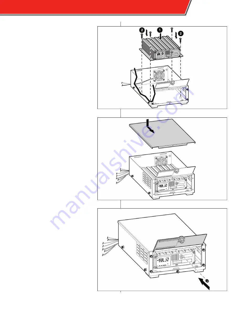
8. 

Place the Observer 4100 in the lock box 

over the raised screw holes and secure 

it using the included screws.

9. 

Replace the lid and push it firmly 

forwards, ensure the tabs in the rear 

engage the back of the lock box.

10. 

Use a T15 security bit to replace the 

central screw under the hinge.

Summary of Contents for OBSERVER 4100

Page 1: ...OBSERVER 4100 USER GUIDE...

Page 2: ...ng but not limited to the implied warranties of merchantability and fitness for a particular purpose Safety Vision shall not be liable for errors contained herein or for incidental or consequential da...

Page 3: ...SV 4100LB 6 Remote Control 8 Live View 10 Menu Navigation 10 Video Playback 11 Exporting Video Files 13 Configuration 14 System Menu 14 Record Menu 22 Network Menu 31 Event Menu 36 Peripheral Menu 45...

Page 4: ...ejects 5 SD Card Slot Door The SD Card Slot Door protects the SD card from contaminants and damage 6 Status LEDs The Status LEDs illuminate to display the current status of the Observer 4100 Flashes w...

Page 5: ...lockwise to lock the door Do not force the SD card into the Observer 4100 upside down or backwards To remove the SD card follow the procedure above press the card into the slot until it clicks then al...

Page 6: ...rn Signal Sensor 1 Right Turn Signal Power Harness Red Power 12 32V DC Black Ground White Ignition Yellow on some models Table A Cable Length SVS 3MMF 10 SVS 5MMF 16 SVS 10MMF 33 SVS 15MMF 49 SVS 20MM...

Page 7: ...tton module is available The panic button provides an additional status LED display remote control sensor and external monitor output in addition to the panic button When the panic button module is in...

Page 8: ...les in the bottom of the lock box three near the front three near the rear 5 Ensure the power and ground leads for the auxiliary fan are threaded through the cable passage in the rear 6 Attach the pow...

Page 9: ...he lock box over the raised screw holes and secure it using the included screws 9 Replace the lid and push it firmly forwards ensure the tabs in the rear engage the back of the lock box 10 Use a T15 s...

Page 10: ...8 OBSERVER 4100 USER GUIDE CP3 Monitor CP4 Monitor...

Page 11: ...e and keys to adjust each value Setup Quickly access the configuration menu Login may be required Exit Quickly return to the previous menu while viewing configuration menus Pressing this key on the ma...

Page 12: ...erver 4100 menu You must login with a password using the number keys on the remote if one has been set in the configuration menu Use the up and down arrow navigational keys to switch between the Video...

Page 13: ...se the provided fields to narrow your search and select the Search button at the bottom of the screen All Files FILE SOURCE Select the source to search SD FILE TYPE Select a specific type of event to...

Page 14: ...IME Displays the time the video recording started and stopped SIZE Displays the size of the file in MB megabits FIRST PGUP PGDW LAST Use the arrow and Enter keys to select these options to scroll thro...

Page 15: ...UTO EXPORT USB field in the General menu see page 15 2 Insert a USB thumb drive into the USB port on the front panel of the Observer 4100 3 Press the F1 key on the remote control A message appears to...

Page 16: ...g System GPS Network Time Protocol NTP or manual NONE TIME ZONE Select how many hours the local time zone is deviated from GMT In the United States Eastern is 5 Central is 6 Mountain is 7 and Pacific...

Page 17: ...on start up Select OFF to require recording be manually triggered ON OFF TYPE IGNITION SHUT DOWN DELAY MIN Use the number keys on the remote control to manually enter the time in minutes that the Obse...

Page 18: ...ranging from 00000 to 99999 COMPANY NO Use the arrow keys on the remote control to enter the name of the agency to which the Observer 4100 belongs VEHICLE ID Use the number keys on the remote control...

Page 19: ...wn menu Available devices include SD inserted SD card or USB inserted USB flash drive 2 In the FUNCTION field select FAST FORMAT to format normally or SLOW FORMAT to search for bad storage sectors bef...

Page 20: ...Upgrade menu 6 Ensure FIRMWARE is selected in the drop down menu to update the MDVR s firmware Additionally select MCU LOGO Update or CP4 to update those devices respectively 7 Select UPGRADE The upda...

Page 21: ...USER same as ADMINISTRATOR rights but cannot change passwords format storage media or export or delete the system log USER may only view video and video logs cannot access configuration menus PASSWORD...

Page 22: ...to revert all settings to the factory defaults EXPORT CURRENT SETTINGS To export all of the current settings to a USB flash drive insert one in the front USB port and select EXPORT The settings are a...

Page 23: ...assist Safety Vision Technical Support in troubleshooting potential issues To export the system log file 1 Insert a USB flash drive into the front USB port 2 Select EXPORT SYSTEM LOG The system log is...

Page 24: ...1 frame per second until an event is triggered when recording will automatically switch to the quality specified in the Record Setting menu This option is useful to conserve storage space ALARM PRE R...

Page 25: ...s near capacity Select OFF to stop all recording video after the storage media is full necessitating manual file deletion LOCKED FILE RETENTION Select the number of days locked files remain locked bef...

Page 26: ...tion is available to be displayed DATE TIME The date and time of the recording ALARM The trigger that initiated the recording if active MODULE STATUS The status of networking modules ACCELERATION The...

Page 27: ...is camera NAME Enter an optional alphanumeric name for each specific camera AUDIO Select ON to enable audio recording for this camera LIVE Select ON to display this camera in the live view SEQUENCE Se...

Page 28: ...e DVR supports 15 FPS if all four channels are set to D1 HD1 and CIF support 30 FPS on all four channels FR Select the frame rate in seconds of this camera Select from 1 to 30 FPS STD REC QUALITY Sele...

Page 29: ...the resolution for this camera when sub streaming Select from CIF or QCIF FR Select the frame rate in seconds of this camera when sub streaming Select from 1 to 30 FPS QUALITY MODE1 only Select the q...

Page 30: ...s recording or ALARM for event based recording in the TYPE field Select the duration of your agency specific work week in the WORKDAY FROM fields This indicates the days scheduled recordings occur whe...

Page 31: ...ect ON in a channel s respective ENABLE field to turn on the cameo functionality The selected channel s camera is then turned off during normal operation and only turns on when an alarm is triggered O...

Page 32: ...proves the validity of recorded video as evidence since it is not as easily tampered with WATERMARK Select ON to insert a watermark on all recorded video Select OFF to record video without a watermark...

Page 33: ...l The Local menu controls network information for the Observer 4100 unit when configuring networks Use the number keys on the remote control to enter the following IP Static internet protocol IP addre...

Page 34: ...USER GUIDE Cellular The Cellular screen controls how the Observer 4100 interfaces with a cellular network for the Observer Management System OMS Enter the cellular network credentials given in the ap...

Page 35: ...OBSERVER 4100 USER GUIDE 33 Server Network The Server Network screen controls central management system CMS server addresses that the Observer 4100 networks with in development at this time...

Page 36: ...IP for WiFi networks requiring a static IP address Select AUTO IP for DHCP enabled WiFi networks IP Static IP address of the access point SUB Subnet mask of the access point GATE Default gateway of th...

Page 37: ...gs The FTP Settings screen controls the user name and password of an optional FTP server to remotely access video files and transfer data to a host server For more information regardling FTP server co...

Page 38: ...or here OSD Press Enter on the remote control to display an on screen keyboard and enter an abbreviated or truncated name of the sensor here This name appears in the OSD while viewing the Live View or...

Page 39: ...n Select NEXT PAGE on the Sensor menu to access this menu The Sensor Trigger menu allows a channel to be displayed in fullscreen while using Live View when an event is triggered For each sensor select...

Page 40: ...gh 4 OUT1 to OUT4 OVER SPEED LOW SPEED HIGH TEMP LOW TEMP and ACCERATION type alarms are controlled by settings in the Speed Temperature and Accerlation menus respectively An ERROR type alam occurs wh...

Page 41: ...lect ON to enable this SPEED event Select OFF to disable it THRESHOLD Use the number keys on the remote control to enter the speed at which the event is triggered ALARM Select ON to enable the ALM LED...

Page 42: ...ote control to enter the amount of force in Gs for each axis X Y and Z at which the event is triggered ALARM Select ON to enable the ALM LED on the front of the Observer 4100 when the THRESHOLD force...

Page 43: ...ON to enable this alarm THRESHOLD Use the number keys on the remote control to enter the maximum or minimum temerature at which an event is triggered ALARM Select ON to enable the ALM LED on the front...

Page 44: ...y to switch between shading and not shading This is useful when the camera s angle of view covers both areas with frequent motion and monitored areas B D SENSITIVE The blind detection feature senses w...

Page 45: ...00 can receive before it automatically disconnects from the CMS or shuts down VOLTAGE OF START Enter the voltage in volts that the vehicle typically drops to during startup the ignition key is turned...

Page 46: ...e control to configure the following EN Select ON to enable the panic button module Select OFF to disable it ALARM Select ON to enable the ALM status LED when the event is triggered This LED continues...

Page 47: ...s parameters that control optional connected peripheral accessories PTZ The PTZ Setup menu provides configuration options for advanced optional cameras Consult with the camera manufacturer for the fol...

Page 48: ...he 232RXD 1 and 232TXD 1 terminals Select NONE if nothing is connected to these terminals COM2 Select the device connected to the 232RXD 2 and 232TXD 2 terminals Select NONE if nothing is connected to...

Page 49: ...f firmware currently installed MCU VERSION The MCU feature is not active at this time DEVICE NAME Displays the name of the storage unit CAPACITY Displays the overall capacity of the stor age unit in g...

Page 50: ...IN HISTORY Displays the highest recorded force in Gs experienced by the optional accelerometer along each axis X Y and Z LOWEST VOLTAGE IN HISTORY Displays the lowest received voltage including the da...

Page 51: ...PS MODULE Displays NORMAL if a GPS module is installed NONE is one is not GPS SIGNAL Displays if the GPS signal received is valid WIFI MODULE Displays NORMAL if a Wi Fi module is installed NONE if one...

Page 52: ...50 OBSERVER 4100 USER GUIDE...

Page 53: ...ol The default IP address is 192 168 002 100 2 Connect the PC to the DVR s RJ 45 port with a standard Ethernet cable 3 Ensure the DVR is receiving power and has started up 4 Set a sequential static IP...

Page 54: ...start or stop recording TALK Click the TALK icon to maximize volume output Additionally you can double click any camera channel to display it in full screen PTZ Controls are not applicable at this tim...

Page 55: ...menu description for information regarding inputs and controls Remember to click SAVE to complete parameter changes Maintenance The Maintenance tab allows you to reboot or shut down the connected Obs...

Page 56: ...inutes Post Event Recording Configurable up to 30 minutes Substreaming 2 Configurable Modes for reduced bandwidth streaming applications Ethernet 10 100 RJ 45 port Wi Fi 802 11 b g WPA GPS Synchronize...

Page 57: ...uality Cameras FPS Hours of Recording CIF 4 Medium 4 5 243 CIF 4 Medium 4 10 121 CIF 4 Medium 4 15 81 CIF 4 Medium 4 30 40 Half D1 4 Medium 4 5 152 Half D1 4 Medium 4 10 76 Half D1 4 Medium 4 15 51 Ha...

Page 58: ...56 OBSERVER 4100 USER GUIDE 56 2 20 in 2 5 in 7 92 in 8 49 in 5 97 in 7 48 in Appendix D Dimensions Minimum cable clearance...

Page 59: ...t has been lost or discarded by the customer to damage to products or parts caused by misuse accident improper installation improper maintenance or use in violation of instructions furnished with the...

Page 60: ...ated in a commercial environment This equipment generates uses and can radiate radio frequency energy and if not installed and used in accordance with the instruction manual may cause harmful interfer...

Page 61: ...OBSERVER 4100 USER GUIDE 59...

Page 62: ...opyright 2016 Safety Vision LLC All Rights Reserved CORPORATE HEADQUARTERS 6100 W Sam Houston Pkwy N Houston TX 77041 5113 Main 713 896 6600 Toll Free 800 880 8855 Fax 713 896 6640 www safetyvision co...

Reviews: