background image


MOBILE DIGITAL VIDEO RECORDER   
USER MANUAL        Ver 1.3 


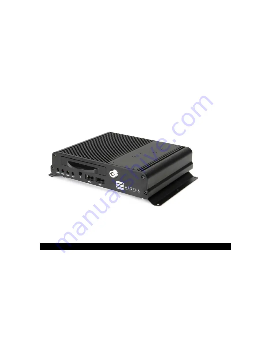
Thank you for purchasing our Mobile DVR. 


Before using the Digital Video Recorder, please ensure that you read and understand 
the User Guide. 


Please store the User Guide at an easily accessible location. 


Before  connecting  and  installing  any  third  party  cameras,  monitors,  alarms  and 
computers, please refer to the appropriate instruction manual for proper operation. 

Summary of Contents for Mobile DVR

Page 1: ...the Digital Video Recorder please ensure that you read and understand the User Guide Please store the User Guide at an easily accessible location Before connecting and installing any third party cameras monitors alarms and computers please refer to the appropriate instruction manual for proper operation ...

Page 2: ...er to the presence of un insulated dangerous voltage within the product s enclosure that may be of sufficient magnitude to constitute a risk of electric shock to persons The exclamation point within an equilateral triangle is intended to alert the user to the presence of important operating and maintenance servicing instructions in the literature accompanying the appliance WARNING TO PREVENT FIRE ...

Page 3: ...Warning 4 Caution 5 Preventing Malfunction 5 1 Controls 8 2 Installation Connection 11 3 Live Monitoring 13 4 Setup Menu 14 5 Search Playback 31 6 Quick Viewer V player 33 7 SmartBlur Privacy Protection 39 8 Specification 42 ...

Page 4: ...irs Stop operating the equipment immediately if it emits smoke or noxious fumes Failure to do so may result in fire or electrical shock Immediately turn the DVR s power off remove the power cable from the power outlet Confirm that smoke and fume emissions have ceased Stop operating the equipment if a heavy object is dropped or the casing is damaged Do not strike or shake Failure to do so may resul...

Page 5: ...ner contents of the battery If the eyes or mouth contact these substances immediately flush with water and seek medical assistance from a medical professional Avoid dropping or subjecting the batteries to severe impacts that could damage the casings It could lead to leakage and injury Do not short circuit the battery terminals with metallic objects such as key holders It could lead to overheating ...

Page 6: ...nsation forms inside the Digital Video Recorder Stop using the equipment immediately if you detect condensation Continued use may damage the equipment Remove the power cord from the power outlet and wait until the moisture evaporates completely before resuming use CAUTION Risk of Explosion if Battery is replaced by an Incorrect Type Dispose of Used Batteries According to the Instructions The socke...

Page 7: ... REMARK Mobile Digital Video Recorder 1 Set Bracket 2 Rubber Dampers and DVR fixing Screws 4 Power Cable 4 pin Wire Type 1 Alarm Cable 8 Pin Wire Type 1 A V IN Cable 2 A V OUT Cable 1 HDD Fixing Screws 4 Device to Bracket Bracket Screws for Bracket fixing 6 Bracket to Vehicle Remote Control 1 Remote Control Battery Coin Type 1 HDD tray Lock Key 1 GPS Antenna 1 CD User Guide in pdf format Client So...

Page 8: ...t types of LEDs show the status of the device 1 Power PWR Green 2 Recording REC Red 3 HDD activated HDD Yellow 4 Network Connected Green 1 1 2 Remote Control Signal Receiver Do not block the receiver port on the unit It may cause the remote control to function improperly ...

Page 9: ...ctor A V IN 8p Camera 1 4 Connectors A V OUT 16p Audio Video Output connector Ethernet port Sensor ALARM IN 1 4 For connecting alarm inputs Relay ALARM OUT A B For connection alarm out relays RS 232 Tx Rx Power Connector DC power plug 12V 24V 10 1 2 3 4 5 6 7 ...

Page 10: ...1 3 Remote Control NOTE PTZ and SPOT are not supported by this model ...

Page 11: ...2 Installation Connection 2 1 Camera Monitor Mike and etc 2 1 1 System Configuration The following illustration is showing the fully configured system of the Mobile DVR ...

Page 12: ...ngle Due to default setting value of shock sensor recommended mounting angle of DVR is basically horizontal If the DVR is to be installing to vertical or any other angles it needs calibration of the shock sensor in the menu of DVR after installation ...

Page 13: ...video loss icon SHOCK HIGH SPEED SPEED LIMIT ACCELERATIOIN DECELERATION It shows you whether there was shock speed limit acceleration and deceleration Quick icons for Mouse Recording Playback Manual Search Log Search Login Audio Network Access Date Day Time Device Status Show you the current date day and time And also shows USB device Wifi connection size of HDD and Expected recoding days with cur...

Page 14: ...d on the Live Viewing screen will appear after a short initialization Press the MENU button to access the main menu An Admin Password Box will appear Enter the password using Numeric buttons on IR remote control Main Menu shown below appears after proper password is entered 4 1 1 Menu Control Method NOTE Factory default Admin user password is 000000 It is recommended to change the password when yo...

Page 15: ...e or choose the value 4 Press ENTER button to exit a menu and save the changes Press CANCEL to exit a menu without saving changes 4 2 Camera Setup In the CAMERA setup menu you can change the value percent of brightness contrast and color the default value percent is 50 ITEM DEFAULT ADJUSTMENT BRIGHTNESS 50 The brightness of each camera can be adjusted with the buttons Selected Not Selected NOTE Ch...

Page 16: ...ed immediate recording is possible after pressing the record button By default the audio alarm and motion recording are off ITEM DEFAULT ADJUSTMENT REC MODE MODE1 Select recording mode with ACC Power ON OFF MODE1 MODE4 AUDIO RECORD OFF ON Turn audio recording ON OFF Turn audio recording OFF BOOTUP RECORD OFF ON Recording will be automatically started when DVR is boot up NOTE By pressing REC button...

Page 17: ... in PAL frames with all resolutions D1 960H Half D1 2CIF CIF Approximate File Size Quality NTSC PAL UNIT 720x480 720x240 360x240 720x576 720x288 360x288 Low 5 1 3 2 2 0 6 1 3 8 2 4 KB s High 7 2 4 5 2 8 8 6 5 4 3 4 KB s NOTE Press MENU button on each Item at first line to apply all settings for the rest of the channels Each of the recording modes are customizable in the Advaced Menu Please see Pag...

Page 18: ...nt Press Cancel button to stop Alarm Out It will be cleared by an order Alarm Motion Video Loss How to use Alarm Output function connection a relay 1 ALARM OUT A ALARM OUT B ALARM OUT is RELAY Switch form ALARM OUT A is connected to GND then using ALARM OUT B by output GND output NOTE If System is selected the relay will be triggered when System has a problem such as recording device failure power...

Page 19: ...OUT B to GND 2 ALARM OUT A is used by signal line 3 When ALARM is triggered supply GND to ALARM OUT A port 3 How to VIDEO LOSS ALARM OUT setting 1 After REC OFF please select MENU DEVICE ALARM a ALARM BUZZER ON b BUZZER TIME 5 MIN c ALALARM OUT VIDEO LOSS ON ...

Page 20: ...n accurate name is not found in the selection Users can choose name of the sensors among them How to use Alarm input function connection a switch panic button 1 Connect Alarm input port CH01 04 Normal High with a panic or switch button 2 After connection with button need to set up on the menu to be activated Alarm input port Select alarm channel you want to configure by using buttons Select the in...

Page 21: ...recognizes and displays it as each alarm 4 4 2 Shock Sensor ITEM DEFAULT ADJUSTMENT SHOCK SENSOR USE ON Select to turn on off the Shock Sensor COODINATE THRESHOLD 1 G Select the threshold value of the shock sensor of each axis An impact over the set threshold value will be recognized and displayed as shock alarm 1 0 3 0g REAL AXIS VALUE NONE Shows current X Y Z value of device ...

Page 22: ...n speed to trigger event alarm DECELERATION 9 Miles h Select the deceleration speed to trigger event alarm AUTO ADJUSTMENT START Press START button to set up current AXIS value as a standard If the DVR is not be installed by horizontal angle If the DVR is to be installing by vertical or other angles it should be needed calibration Shock Sensor Calibration Procedure 1 Mount the DVR which you desire...

Page 23: ...MS ITEM ADJUSTMENT SERVER Enter IP address of PC which ACMS is installed PORT Enter port of PC which ACMS is installed This Port should be port forwarded to the ACMS PC Port forwarding could be setup by router PACKET CYCLE ...

Page 24: ...onnect wifi MANUAL MENU You can manually enter target wifi router and connect it with its password CONNECTION INFO It shows the status of the wifi connection Below is the screen shot of Wizard menu of wifi It shows that the DVR is scanning Wifi Router ...

Page 25: ...enu for wifi setup 4 5 3 ETHERNET If you want to use this DVR as normal standalone DVR or connect DVR via RJ45 connector for local network and local monitoring you need to put the IP address Netmask Gateway DNS server and Access port ...

Page 26: ...y DNS Server IP address ACCESS PORT Enter Port Number Default is 7000 4 6 System Setup 4 6 1 GENERAL ITEM DEFAULT ADJUSTMENT VOLTAGE LIMIT 11 60 V Choose the minimum voltage to stop the recording when the voltage reaches the limit DELAY TIME 0 Min Choose the recording time after ACC off For example If you choose 30Min the DVR will be recording 30 minutes after ACC off ...

Page 27: ...n screen CAMERA Select to show camera number on main screen or unselect to hide BORDER LINE Change color of border line between cameras BLACK DARK GRAY GRAY WHITE BACKGROUND Change background color of NO VIDEO status GRAY WHITE BLUE BLACK DARK GRAY SPEED Select the measure of speed M H or K H ...

Page 28: ...the Time HH MM SS GPS SYNC If the DVR is connected with GPS the time of the device can be synced with the time information received by the GPS ON Default Set the DVR clock according to the time information received by the GPS OFF Set the time manually and do not sync with GPS NOTE Please STOP the recording before adjusting the Time Settings ...

Page 29: ...MENT FORMAT 1 Stop the recording before formatting the internal HDD 2 Press START button to start 4 Format status is displayed on screen DISK MONITOR To check the condition of the HDD Choose START and Press it 4 6 5 VEHICLE ...

Page 30: ...USTMENT EVENT BUZZER Turn on or off the buzzer of DVR KEY TONE To turn on or off the key tone of remote control LANGUAGE Choose your language with DVR VIDE MODE Choose video type NTSC or PAL SYSTEM PASSWORD You can change the password of DVR FACTORY DEFAULT Press START if you want to setup all your configuration as factory default ...

Page 31: ... to select a day on the Calendar Selected data will be shown as a graphical representation of the recorded video stored on the DVR 4 Select by the time or camera you wish to playback from then press the ENTER button 5 Press the ENTER button to start playback NOTE The date will not change if there is no stored data on the previous or next month NOTE The data is color coded by category Alarm Red Mot...

Page 32: ...he Log List Menu will pop up as shown below MENU TAB CONDITION All A list of all events since the initial power on procedure of device System All system events except for Alarm Motion and Video Loss Network N A Alarm All alarm incidents are logged Motion All motion incidents are logged VLoss All video loss incidents are logged 2 Use the Up Down buttons to select the desired incident to playback Us...

Page 33: ...at does not need to be installed on the PC It will be saved to the SD Card automatically 6 1 Operation 1 Once an SD card with recorded data is inserted into the PC open the SD card folder 2 Double click the icon vplayer lite exe to launch the quick viewer ...

Page 34: ... display When folder with data is selected this icon is activated with host name or vehicle name in the device If folder is not selected it is not activated Display option Multi screen Displays Map On Off Vehicle position centralization On Off While turned on during playback the device will be centralized on the map Screen shot System log data ...

Page 35: ...ion 1 Display OSD Display Select option which user wants to display on the channel Units Select speed option between KMH or MPH 2 Events User can set up event name without Motion and Video Loss 3 Video Flip Rotate Flip or rotate the image per channel 40 ...

Page 36: ...back previous record file Playback afterword record file Playback timeline A Local time on PC B Recorded file time duration Event record time line Motion record time line Audio On Off Audio volume 6 2 3 Video display If there is no video display it shows in the screen It is different with VideoLoss Blue edge covers selected channel ...

Page 37: ...er can change channel by draging and droping 6 2 4 MAP and GPS information Shows GPS information of device and driving location This icon shows where the device was on the map at that time This icon shows car moving direction Google maps will be displayed when connected to the internet ...

Page 38: ...olor coded by category Event Red Motion Blue Normal Green Record data Tree Data Filter All Data Show days with all record data Event Show days with event record data Motion Show days with motion record data Record data icon in date Normal record data Motion record data Event record data Motion and Event record data ...

Page 39: ...rding data of selected date will be displayed by 5 minutes unit First row shows Time Second row shows recorded data for 5 Minutes unit Color bar info No data recorded Normal record data Motion record data Event record data Motion and Event record data Overlay image ...

Page 40: ...he video to protect privacy User can modify and save recording file as avi file format to desired folder by using a SmartBlur function for privacy protection 7 1 How to use the SmartBlur function Click Convert to avi icon Path Select path for saving file Select recording file to convert 39 ...

Page 41: ...h Select Select Channel which wants to convert Ch1 Ch4 Select Channel which you want to add Blur Mosaic to desired video Create Blur or delete Grid Control User can change size of the created Mosaic Blur ...

Page 42: ... Select the section which user wants to save by using S Start and E End button Convert to Avi Start convert SmartBlur video file ...

Page 43: ...0 Front Storage 2 5 SATA HDD SSD RACK 2TB max size Alarm input 4 TTL Alarm output 1 Relay Network 10 100 1000 Ethernet Wifi wireless using wifi dongle Super Cap Assistant battery Sustainment time 5 sec Working temperature 20 C 60 C 4 F 140 F Storage temperature 40 C 85 C 40 F 185 F Working Humidity 0 90 Sleep leakage current 3Ma External power output 12V 1 5A Working Voltage DC 12V 24V Current con...

Page 44: ...environment or human health from uncontrolled waste disposal please separate this from other types of wastes and recycle it responsibly to promote the sustainable reuse of material resources Household users should contact either the retailer where they purchased this product or their local government office for details of where and how they can take this item for environmentally safe recycling Bus...

Reviews: