background image

B

-  

10

TIGMATE  

270  

AC/DC  

–  

TIGMATE  

400  

AC/DC

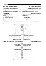
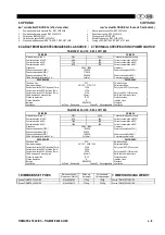
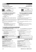
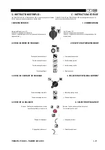
B - MISE EN SERVICE

/

B - STARTING UP 

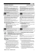
1. DÉBALLAGE DE L'INSTALLATION /

1. UNPACKING THE SET 

Retirer le carton qui entoure l'installation.

Remove the cardboard surrounding the set.

Retirer la source de puissance de son socle en bois à l'aide d'élingues

Remove the power source from its wooden base using slings.

ATTENTION

Elinguer IMPERATIVEMENT par les 4

anneaux d'élinguage.

CAUTION 

Slinging only with sling attachments.

2. RACCORDEMENT ÉLECTRIQUE AU RÉSEAU /

2. ELECTRICAL CONNECTIONS TO THE MAINS 

 

 

 

voir  dépliant  FIGURE  4  à  la  fin  de  la  notice)

(  

 

 

 

 see leaflet FIGURE 4 at the end of instructions)

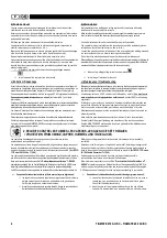
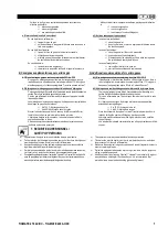
Les TIGMATE 270 AC/DC et TIGMATE 400 AC/DC sont livrés :

TIGMATE 270 AC/DC and TIGMATE 400 AC/DC are delivered with:

câble primaire branché dans le générateur 

the primary cable connected to the generator 

couplage en 400 V

400V 

 coupling 

Les fréquences réseau acceptées sont :

The mains frequencies accepted are

50 et 60 Hz

50 and 60 Hz 

Si votre réseau correspond au couplage usine, il suffit donc de brancher une prise
"monophasé + terre" adaptée à la puissance du générateurà l'extrémité du câble

d'alimentation.
L’alimentation doit être protégée par un dispositif de protection (fusible ou disjoncteur)

de calibre correspondant à la consommation primaire maximum du générateur ( voir 
page 10 )

If your mains corresponds to factory coupling, just connect a "single-phase + earth" 

connector suited to the generator power on the power cable end.
The power supply must be protected by a protection device (fuse or circuit breaker)

with rating corresponding to the maximum primary consumption of the generator (refer 

to page 10).

Si votre réseau correspond à une

autre tension d'alimentation

, il est nécessaire de

changer le couplage à l'intérieur de la source de puissance.

If your mains corresponds to

another power supply voltage

, the coupling inside the

 power source must be changed.

Pour cela :

To do this

mettre le poste hors tension

switch the set off.

enlever le panneau droit du générateur en retirant les vis qui le fixent.

remove the RH panel of the generator by removing the screws securing it.

adapter le couplage à la tension du réseau d'utilisation suivant les
indications données dans le générateur et ci-après

adapt the coupling to the operating mains voltage as per instructions given in

the generator and below.

remonter le panneau latéral en replaçant

toutes

 les vis de fixation.

. re-install the side panel by installing

all 

 fastening screws.

3. RACCORDEMENT DE L'ARRIVÉE DE GAZ (SUR DÉTENDEUR) /

3

.

GAS INLET CONNECTION (ON PRESSURE REGULATOR)

 

 

 

voir  dépliant  FIGURE  5  à  la  fin  de  la  notice)

(  

 

 

 

 see leaflet FIGURE 5 at the end of instructions)

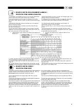
Le tuyau de gaz est associé au générateur. Il suffit de le raccorder à la sortie du

détendeur sur la bouteille de gaz comme indiqué ci-après.

The gas hose is associated with the generator.  Just connect it to the pressure

regulator outlet on the gas cylinder as indicated below.

Mettre la bouteille de gaz sur le chariot à l'arrière du générateur et fixer la
bouteille à l'aide de la sangle.

Place the gas cylinder on trolley at the rear of the power source and fasten

the cylinder by means of the strap.

Ouvrir légèrement puis refermer le robinet de la bouteille pour évacuer 
éventuellement les impuretés.

Open the cylinder valve slightly and close it to allow any impurities to

escape.

Monter le détenteur/débitmètre.

Fit the pressure regulator/flowmeter.

Raccorder le tuyau gaz livré avec le générateur sur la sortie du détendeur.

Connect the gas hose delivered with the power source to the pressure-

regulator outlet.

Ouvrir la bouteille de gaz.

Open the gas.

En soudage, le débit de gaz devra se situer entre 15 et 20l/min.

In welding, the gas flow rate should be between 15 and 20l/min.

ATTENTION

Veiller à bien arrimer la bouteille de gaz en mettant en place une
sangle de sécurité.

CAUTION 

Be careful to secure the gas cylinder by putting a safety strap back in place.

4. RACCORDEMENT EQUIPEMENT /

4. EQUIPMENT CONNECTION 

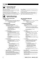
Les raccordement se font à l'avant du générateur 
.

 ( 

 

 

 

 voir dépliant FIGURE 6 à la fin de la notice

Connections are at the front of the generator.

.

 ( 

 

 

 

 see leaflet FIGURE 6 at the end of instructions)

Vérifier que l’interrupteur 0/1 est sur la position 0.

Check that switch 0/1 is on position 0.

En mode TIG :

Raccorder la torche TIG sur la borne A et la prise de masse sur la borne B.

In TIG mode:

Connect the TIG torch to terminal A and the ground connector to terminal B.

Raccorder le câble de commande de la torche sur le socle C

Si torche eau :
Vérifier si le shunt existe dans la rpise de commande gachette suivant le type de

torche eau (voir plan du TIGMATE 270/400 AC/DC)

Connect the power cable of the torch to base C.

With a water torch :

Check if the shunt exists in the order tacking trigger, according to the type of water 

torch (see drawing TIGMATE 270/400 AC/DC)

En mode électrode enrobée:

In covered electrode mode:

Raccorder la prise de la pince porte électrode sur la borne A ou B du générateur.

Connect the electrode holder connector to terminal A or B of the generator.

Raccorder  la prise de masse sur la borne restante

Connect the ground connector to the remaining terminal.

Respecter les polarités indiquées sur l’embalage du paquet d’électrodes utilisés.

Observe polarities indicated on the packaging of the used electrode package.

Summary of Contents for TIGMATE 270 AC/DC

Page 1: ...REZZA D UTILIZZO E DI MANUTENZIONE DI MANUTENZIONE INSTRUCCION INSTRUCCIONES DE ES DE SEGURIDAD EMPLEO Y SEGURIDAD EMPLEO Y MANTENIMIENTO MANTENIMIENTO INSTRU ES DE SEGURAN A E DE MANUTEN O INSTRU ES...

Page 2: ......

Page 3: ......

Page 4: ...IAGRAMS AND FIGURES ELECTRICAL DIAGRAMS AND FIGURES 71 71 INHALTSVERZEICHNIS INHALTSVERZEICHNIS INDICE INDICE SICHERHEITSHINWE SICHERHEITSHINWEISE ISE REGOLE DI SICUREZZA REGOLE DI SICUREZZA 20 20 A A...

Page 5: ...INSTALLATIE 1 BESKRIVNING AV MASKINEN ERREUR SIGNET NON D FINI 2 SAMENSTELLING 2 SVETSAGGREGATETS OLIKA DELAR ERREUR SIGNET NON D FINI 3 TIGMATE 270 AC DC BESCHRIJVING VAN HET VOORPANEEL 3 FRONT PANE...

Page 6: ...curit contre les fum es les vapeurs les gaz nocifs et toxiques cf page 4 3 s curit contre les rayonnements lumineux cf page 5 4 s curit contre le bruit cf page 5 5 s curit contre le feu cf page 6 6 s...

Page 7: ...very six months you must check the proper condition of the insulation and connections of the electric equipment and accessories such as plugs flexible wires ducts connectors extensionleads part holder...

Page 8: ...number may be used 2 L expression m taux lourds couvre les aciers les aciers alli s le cuivre et ses alliages etc 2 The expression heavy metals covers steels alloyed steels copper and its alloys and s...

Page 9: ...the impermeability of the fixed piping as well as the rubber tubing ne d tectez jamais une fuite avec une flamme Utilisez un d tecteur appropri ou d faut de l eau savonneuse et un pinceau never use a...

Page 10: ...ventilationattheplaceswhichareatrisk C est un gaz inflammable La flamme d hydrog ne est presque invisible risques de br lures This is an inflammable gas The hydrogen flame is almost invisible risks of...

Page 11: ...rnatif continu 5 Selection of welding current alternating direct Interrupteur 0 1 6 Switch 0 1 Potentiom tre r glage balance 7 Balance adjustment potentiometer S lection du mode de soudage 8 Selection...

Page 12: ...10mn 270A Duty cycle 60 10min cycle C ble de masse 5 m avec prise 35mm Earth cable 5 m with clamp Classe de protection IP 23 Protection class Classe d isolation H Isolation class Normes EN 60974 1 St...

Page 13: ...REGULATOR voir d pliant FIGURE 5 la fin de la notice see leaflet FIGURE 5 at the end of instructions Le tuyau de gaz est associ au g n rateur Il suffit de le raccorder la sortie du d tendeur sur la b...

Page 14: ...r is switched on voltage selected on the terminal board 2 CHOIX DU MODE DE SOUDAGE 2 SELECTION OF WELDING MODE Position lectrodes enrob es Covered electrode position Position soudage 2 temps 2 action...

Page 15: ...s risques de fissuration 1 0 2 3 4 5 6 7 8 9 10 Fadingadjustment Avoids craters at weldingends and risk of cracking R glage post gaz Prot ge la pi ce et l lectrode tungst ne de l oxydation apr s la so...

Page 16: ...ement provoque l amor age avec HF la mont e progressive du courant de soudage et le courant de soudage Une seconde impulsion sur la gachette provoque vanouissement de l arc jusqu extinction compl te a...

Page 17: ...appe 8 conducteurs sur le circuit imprim de l option Connect the 8 conductor harness to the printed circuit of the option 1 D monter la t le c che 1 Remove the cover plate 2 A sa place fixer la t le d...

Page 18: ...the rear panel 2 Glisser l unit de refroidissement dans le g n rateur et raccorder le connecteur du g n rateur avec celui de l unit de refroidissement 2 Slide the cooling unit into the generator and...

Page 19: ...ec un aspirateur ou par soufflage l air comprim sec apr s purge des tuyaux et du r servoir Remove all dust from the apparatus if possible with a dust extractor or by blowing dry compressed air after d...

Page 20: ...s 48V 2 contacts RT Relay 48V 2 contacts RT 26 4079 6027 Relais 48V 3 contacts RT Relay 48V 3 contacts RT 27 4012 4230 Carte RC TIG AC DC Board RC TIG AC DC 28 4088 6042 Shunt 500A 0 1V 400A 0 1V Shun...

Page 21: ...rcuit 24 4088 2176 Self Coil 25 4079 6028 Relais 48V 2 contacts RT Relay 48V 2 contacts RT 26 4079 6027 Relais 48V 3 contacts RT Relay 48V 3 contacts RT 27 4012 4230 Carte RC TIG AC DC Board RC TIG AC...

Page 22: ...eplace fuses F3 F4 Pas de commande cycle Remplacer le fusible F2 48V No cycle control Replace fuse F2 48V ECHAUFFEMENTTROPIMPORTANT VOYANTORANGEALLUME OVERHEAT DEFECT LIGHT ON D passement du facteur d...

Page 23: ...heSeite20 2 Schutz vor Rauch D mpfen und giftigen Gasen siehe Seite 21 3 SchutzvorLichtstrahlung sieheSeite22 4 L rmschutz sieheSeite22 5 Brandschutz sieheSeite22 6 Sicherheit beim Umgang mit Gas sieh...

Page 24: ...erungen Masseklemme Elektrodenhalter Brennerusw Dovete verificare almeno ogni 6 mesi il buono stato d isolamento ed i collegamenti degli apparecchi e degli accessori elettrici come prese cavi flessibi...

Page 25: ...rmalerweise keine Schwei techniken angewandt werden Nota le zone trattegiate di cui sopra corrispondono ai campi dove i processi di saldatura non sono abitualemnte utilizzati nella pratica attuale del...

Page 26: ...i gas alle pressioni raccomandate nei manuali d istruzioni forniti con i materiali Lassen Sie die Schl uche nicht auf dem Boden liegen Sie k nnen sonst besch digt werden non lasciate mai i tubi sparsi...

Page 27: ...tnissen Mischungsverh ltnissen Le miscele aria idrogeno ed ossigeno Le miscele aria idrogeno ed ossigeno idrogeno sono esplosive negli idrogeno sono esplosive negli intervalli di proporzioni elevate i...

Page 28: ...ro di regolazione bilanciamento W Wa ah hl d l de er S r Sc ch hw we eii a ar rt t 8 8 Selezione della modalit di saldatura Selezione della modalit di saldatura Po Pote tent ntio iome mete ter r Na Na...

Page 29: ...0min M Ma as ss se ek ka ab be ell 5 5 m m m miit t K Klle em mm me e 3 35 5m mm m Cavo di massa 5 m Cavo di massa 5 m con morsetto con morsetto S Siic ch he er rh he eiit ts ss st tu uf fe e I IP P 2...

Page 30: ...dieser Anleitung si veda l opuscolo FIGURA 5 sul retro del libretto Der Gasschlauch geh rt zum Generator und braucht nur noch hinter dem Druckminderer an die Gasflasche wie nachstehend aufgef hrt ang...

Page 31: ...vizio tensione selezionata sulla morsettiera 2 WAHL DER SCHWEISSART 2 SCELTADELLAMODALITA DISALDATURA Position Schwei en mit umh llten Elektroden Posizione elettrodi rivestiti Position2 Takt Schwei en...

Page 32: ...hwei vorgangs Sch tzt weitgehend vor Ri bildung 1 0 2 3 4 5 6 7 8 9 10 Regolazione del fader Evita il cratere di fine saldatura e i rischi di fessure Einstellung Nachgas Sch tzt das Werkst ck und die...

Page 33: ...tensivierung des Schwei stroms bis zur Normalleistung Ein zweiter kurzer Hebeldruck bewirkt die Abschw chung des Lichtbogens bis zum vollst ndigen Erl schen Ausschalten des Schwei stroms und Austritt...

Page 34: ...opuscolo FIGURA 7 sul retro del libretto Haube des Generators abheben Togliere il coperchio del generatore Auflage mit den 8 Leitern am gedruckten Schaltkreis aus dem Sonderzubeh r anschlie en Collega...

Page 35: ...tblatt ABB 10 am Ende dieser Anleitung Montaggio si veda l opuscolo FIGURA 9 alla fine del libretto 1 Unteres Abdeckblech an der R ckseite abnehmen 1 Smontare la lamiera di copertura inferiore sul lat...

Page 36: ...entstauben nach Leeren der mit dem Tank verbundenen Schl uche Rimuovere tutta la polvere dall apparecchio se possibile con un estrattore di polvere o spolverando con aria compressa asciutta dopo aver...

Page 37: ...6028 Rel 48V 2 RT Kontakte Rel 48V 2 contatti RT 26 4079 6027 Rel 48V 3 RT Kontakte Rel 48V 3 contatti RT 27 4012 4230 RC Karte f r TIG AC DC Scheda RC TIG AC DC 28 4088 6042 Shunt 500A 0 1V 400A 0 1...

Page 38: ...4088 2176 Selbstinduktionsspule Autoinduzione 25 4079 6028 Rel 48V 2 RT Kontakte Rel 48V 2 contatti RT 26 4079 6027 Rel 48V 3 RT Kontakte Rel 48V 3 contatti RT 27 4012 4230 RC Karte f r TIG AC DC Sch...

Page 39: ...schen Comando ciclo assente Sostituire il fusibile F2 48V ZU STARKE ERHITZUNG ORANGEKONTROLLEUCHTELEUCHTETAUF SURRISCALDAMENTO SPIA ARANCIONE ACCESA berschreitendeseingestellten Einschaltdauer Warten...

Page 40: ...gina 37 2 seguridad contra humos vapores y gases nocivos y t xicos v ase la p gina 38 3 seguridad contra las radiaciones luminosas v ase la p gina 39 4 seguridad contra el ruido v ase la p gina 39 5...

Page 41: ...ficarpelomenosde6em6meses seasisola eseasliga esdosaparelhose dosacess riosel ctricostaiscomo tomadas cabosflex veis condutas conectores prolongadores pin asdepe as porta el ctrodosoutochasest oembome...

Page 42: ...o podem se utilizar o n mero de escala imediatamente superior ou o num ro de escala imediatamente inferior 2 La expresi n metales pesados abarca los aceros los aceros aleados el cobre y sus aleacione...

Page 43: ...eriodicamente a estanquecidade das canaliza es fixas assim como das tubagens em borracha no detecte nunca una fuga con una llama Utilice un detector apropiado o en su defecto agua jabonosa y un pincel...

Page 44: ...quemaduras um g s inflam vel A chama do hidrog nio quase invis vel risco de queimaduras Las mezclas aire hidr geno y ox geno hidr geno son explosivas en gamas de proporciones amplias As misturas ar h...

Page 45: ...orrente de soldadura alterna cont nua Interruptor 0 1 6 Interruptor 0 1 Potenci metro de ajuste balanza 7 Potenci metro ajuste balan a Selecci n delmododesoldadura 8 Selec o do modo de soldadura Poten...

Page 46: ...de marcha 35 ciclo de 10min Cable de masa 5 m con toma 35mm Cabo de massa 5 m com ficha Clase de protecci n IP 23 Classe de protec o Clase de aislamiento H Classe de isolamento Normas EN 60974 1 Norma...

Page 47: ...EDUCTOR 3 LIGA O DA CHEGADA DE G S NO MANORREDUTOR v ase folleto FIGURA 5 al final de las instrucciones ver desdobr vel FIGURA 5 no fim do manual El tubo de gas est integrado en el generador Basta con...

Page 48: ...servi o tens o seleccionada na placa de terminais 2 ELECCI N DEL MODO DE SOLDADURA 2 ESCOLHA DO MODO DE SOLDADURA Posici n electrodos revestidos Posi o el ctrodos revestidos Posici n soldadura 2 tiem...

Page 49: ...fisuraci n 1 0 2 3 4 5 6 7 8 9 10 Ajuste desvanecimento Evita a cratera no fim de soldadura e os riscos de fissuras Ajuste pos gas Protege la pieza y el electrodo de tungsteno de la oxidaci n despu s...

Page 50: ...oltar provoca el cebado con HF la subida progresiva de la corriente de soldadura y la corriente de soldadura Una segunda presi n sobre el gatillo provoca el apagado gradual del arco hasta su extinci n...

Page 51: ...tampa do gerador Conectar la capa de 8 conductores en el circuito impreso de la opci n Ligar o cabo 8 condutores no circuito impresso da op o 1 Desmontar la chapa de tap 1 Desmontar a chapa tampa 2 A...

Page 52: ...seira 2 Introducir la unidad de refrigeraci n en el generador y conectar el conector del generador con el de la unidad de refrigeraci n 2 Introduzir a unidade de refrigera o no gerador e ligar o conec...

Page 53: ...aspirador o por soplado con aire comprimido seco despu s de purgar los tubos y el dep sito Retirar o p do aparelho se poss vel com um aspirador ou soprando com ar comprimido seco depois de purgar as t...

Page 54: ...tos RT Rel 48V 2 contactos RT 26 4079 6027 Rel 48V 3 contactos RT Rel 48V 3 contactos RT 27 4012 4230 Tarjeta RC TIG AC DC Carta RC TIG AC DC 28 4088 6042 Shunt 500A 0 1V 400A 0 1V Shunt 500A 0 1V 400...

Page 55: ...4088 2176 Self Self 25 4079 6028 Rel 48V 2 contactos RT Rel 48V 2 contactos RT 26 4079 6027 Rel 48V 3 contactos RT Rel 48V 3 contactos RT 27 4012 4230 Tarjeta RC TIG AC DC Carta RC TIG AC DC 28 4088...

Page 56: ...F3 F4 No hay mando de ciclo Cambiar el fusible F2 48V Sem comando ciclo Substituir o fus vel F2 48V CALENTAMIENTOEXCESIVO INDICADOR LUMINOSO NARANJA ENCENDIDO AQUECIMENTO DEMASIADO IMPORTANTE INDICADO...

Page 57: ...veiligheid cf page 54 2 veiligheidsmaatregelentegenrook dampen schadelijkeen giftige gassen se sida 55 3 veiligheidsmaatregelentegenlichtstralen cf page 56 4 veiligheidsmaatregelentegengeluidshinder c...

Page 58: ...op met SAF voor onderhoudofherstellingen Vissa apparater best r av en HT HF t ndningskrets anges med en skylt Du f r aldrig ingripa i denna krets kontakta SAF f r allt ingrepp U controleert om de 6 m...

Page 59: ...mask som best r av ett l mpligt skyddsfilter Onderstaande tabel geeft de graadschaal 1 en het aanbevolen gebruik voor lasboogwerken Tabell som anger skyddsniv n 1 och rekommenderad anv ndning f r b gs...

Page 60: ...t t ta spoor een lek nooit op met een vlam Gebruik een aangepaste detector of anders zeepsop en een borsteltje s k aldrig efter l ckage med hj lp av en l ga Anv nd en l mplig sensor eller vatten med t...

Page 61: ...n echter nagenoeg onzichtbaar gevaar voor brandwonden Det r en l ttant ndlig gas L gan fr n v te r n stan osynlig risk f r br nnskador Lucht waterstofmengselsenzuurstof waterstofmengselszijn ontplofba...

Page 62: ...1 6 Str mbrytare0 1 Potentiometer balansinstelling 7 Potentiometer f r inst llning av balans Keuzeschakelaarlasmodus 8 Val av svetsmetod Potentiometer postgas instelling 9 Potentiometer f r inst llnin...

Page 63: ...Werkingsfactor 35 cyclus van 10 min 270A Intermittensfaktor 60 10 min cykel Aardingskabel 5 m met klem 35mm Jordkabel 5 m med kontakt Beveiligingsklasse IP 23 Skyddsklass Isolatieklasse H Isolationskl...

Page 64: ...rug en draai alle bevestigingsschroevenvast termontera sidostycket genom att s tta tillbaka alla f stskruvar 3 DE GASAANVOER AANSLUITEN OP DE REDUCEERKLEP 3 GASINLOPPSKOPPLING P TRYCKREGULATOR zie fol...

Page 65: ...ret 0 1 Position 0 generatorn r fr nslagen Position 1 generatorn r i drift vald sp nning p uttagsplattan 2 DE LASMODUS KIEZEN 2 VAL AV SVETSMETOD Stand beklede elektroden Position kl dda elektroder 2...

Page 66: ...r en scheurvorming bij het stoppen met lassen 1 0 2 3 4 5 6 7 8 9 10 Utsl ckningsinst llning Undviker kratern i slutet av svetsningen och risker f r sprickbildning Postgas instelling Beschermt het wer...

Page 67: ...uitgevoerd ontsteking met HF geleidelijk opwekken van de lasstroom en de lasstroom Als u de trekker een tweede keer indrukt de boogvlam dooft geleidelijk de lasstroom stopt en tenslotte de postgas fas...

Page 68: ...ork pan Sluit de 8 pins connector aan op de optionele printplaat Anslut 8 stiftskontakten p optionens kretskort 1 Demonteer de dekplaat 1 Demonteraskyddspl ten 2 Monteer in plaats hiervan de plaat van...

Page 69: ...10 i slutet av notisen 1 Demonteer de plaat van de onderste dekplaat op het voorpaneel 1 Demontera den undre skyddspl ten p baksidan 2 Schuif de koelunit in de generator en sluit de connector aan op d...

Page 70: ...erslucht na het aftappen van de leidingen en de tank Avl gsna allt damm fr napparaten om m jligtmed ett dammutsug eller genom bl sning med torr tryckluft efter t mning av slangar och tank Controleer d...

Page 71: ...ntacten Rel 48V 3 RT kontakter 27 4012 4230 Kaart RC TIG AC DC Kort RC TIG AC DC 28 4088 6042 Shunt 500A 0 1V 400A 0 1V Shunt 500A 0 1V 400A 0 1V 29 4045 6021 Gelijkrichter TIG AC DC 270A Likriktare T...

Page 72: ...acten Rel 48V 2 RT kontakter 26 4079 6027 Relais 48V 3 RT contacten Rel 48V 3 RT kontakter 27 4012 4230 Kaart RC TIG AC DC Kort RC TIG AC DC 28 4088 6042 Shunt 500A 0 1V 400A 0 1V Shunt 500A 0 1V 400A...

Page 73: ...g F3 F4 Byt s kringarna F3 F4 Geen cyclusbesturing Controleer de zekering F2 48V Ingetcykelkommando Byt s kringen F2 48V EXCESSIEVE VERHITTING ORANJE LED AAN VERHETTNING ORANGE SIGNALLAMPA LYSER De we...

Reviews: