background image

Phoenix G2 IDU User Manual                                                                         WEB GUI 


SAF Tehnika JSC                                                                                                                                                 

         50 

Chapter 3:

 WEB GUI


Initial configuration 

System requirements 

To access PhoeniX G2 IDU Web GUI you will need a PC with the following system 
requirements: 

Operating system 


Microsoft Windows XP / Vista / 7 / 8/10; 


Linux 

Web browser 


Google Chrome; 


Mozilla Firefox; 


Internet Explorer 8 (or above) 


Ethernet management connection configuration 

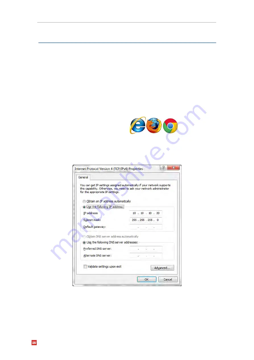
Before proceeding with initial link setup in Web GUI, you must adjust IPv4 settings of your LAN 
adapter to 10.10.10.0 subnet. IP address should be other than default IP address (10.10.10.10). 


Figure 3.1 

TCP/IPv4 Properties


After applying these settings you are ready to connect to Web GUI or establish SSH/Telnet


connection. 

USB Management connection configuration 

In case MNG USB B serial port is used for Web GUI access, following steps can be taken: 

Summary of Contents for Phoenix G2 IDU

Page 1: ...User manual Phoenix G2 IDU VER 1 10 FW 0403_04 ...

Page 2: ...s These limits are designed to provide reasonable protection against harmful interference in a residential installation This equipment generates uses and can radiate radio frequency energy and if not installed and used in accordance with the instructions may cause harmful interference to radio communications However there is no guarantee that interference will not occur in a particular installatio...

Page 3: ... HP ODU with SAF2 adaptation interface 43 Cable requirements 46 Powering Phoenix G2 IDU ODU 48 Powering External Multiplexer Modules EMM 49 Powering Phoenix G2 IRFU 49 Chapter 3 WEB GUI 50 Initial configuration 50 System requirements 50 Ethernet management connection configuration 50 USB Management connection configuration 50 Accessing PhoeniX G2 IDU Web GUI 51 Web GUI description 52 Button conver...

Page 4: ...enance Configuration Save Run 96 Maintenance Configuration Backup Restore 97 Maintenance Configuration Factory default 98 Maintenance Firmware Upgrade 98 Maintenance Firmware EMM 99 Maintenance Files Exports 100 Maintenance Files Upload 101 Maintenance Logs 101 Maintenance Troubleshooting Assistant 102 Maintenance Troubleshooting Detail SYS 103 Maintenance Troubleshooting Detail IF 103 Maintenance...

Page 5: ...d frequency protection scheme 146 Example 10 2 2 FD aggregation HSB SD protection scheme 166 Example 11 2 2 FD aggregation FD protection scheme 172 Example 12 2 2 XPIC aggregation HSB SD protection scheme 178 Example 13 2 2 XPIC aggregation FD protection scheme 184 Example 14 1 1 HSB SD Full protection scheme 191 Example 15 1 1 FD Full protection scheme 196 Example 16 VLAN configuration 202 Append...

Page 6: ...city of 452Mbps it is possible to configure the radio to any of 10 14 20 25 28 30 40 50 56 and 60 MHz channels as well as to any of QPSK 16QAM 32QAM 64QAM 128QAM 256QAM 512QAM and 1024QAM modulations thus providing various capacities to suit particular needs SAF Tehnika has employed most modern design solutions and components to create high performance split mount system with low power consumption...

Page 7: ...ational distance is 5 5 meters IDU mechanical features 1U high Power consumption 30W Dimensions 45x210x240 mm weight 2 22 kg Figure 1 1 Phoenix G2 IDU ODUs mechanical features Compact unit 288x288x80mm 3 5kg SP HP ODUs 280x437x110mm 7 5kg VHP ODU 3 handles SP HP ODU and 1handle VHP ODU for user convenience Safe and easy to use 4 side locking tightening arrangement All connectors on the side of the...

Page 8: ...uct model name PhoeniX G2 IDU for PhoeniX G2 Indoor Unit CFIP 18 PhoeniX for 18GHz Outdoor Unit etc Product Number Model Number P N or M N EAGXU002 S18RFU05LA product model number contains information about the unit Serial Number 355260100007 the serial number uniquely identifies the unit Figure 1 4 Label of the PhoeniX G2 Indoor Unit Figure 1 5 Label of the PhoeniX G2 ODU ...

Page 9: ...ich ODU operates H L A designates the subband in which ODU operates A B C Figure 1 6 Label of the PhoeniX G2 IRFU P N Translation for CFIP PhoeniX G2 IRFU S designates CFIP split mount series product 06 designates Frequency range 6 GHz of the Unit RI designates IRFU radio U designates unified band radio operating 7 60MHz 01 designates the version number of the Unit L designates the band side in wh...

Page 10: ...re used also for interconnecting IDUs in case of 1 1 full protection configuration and for IDU interconnection with EMM modules 2 5 Gbps optical fibre cable and SFP modules must be used to interconnect Phoenix G2 IDUs in 1 1 full protection mode 1 Gbps optical fibre cable and SFP modules can be used to interconnect Phoenix G2 IDU with EMM modules LAN1 LAN2 ports 10 100 1000Base Tx Ethernet traffic...

Page 11: ...ss of synchronization STATUS Orange OK no alarms present Orange blinks one or several alarms are active SFP 1 4 Orange SFP port connected Off SFP port not connected Power Green power supply is OK Ethernet RJ 45 connector LED indications Application Examples PhoeniX G2 1 0 configuration Basic split mount 1 0 system with up to 452 Mbps Ethernet Figure 1 8 PhoeniX G2 1 0 configuration PhoeniX G2 1 0 ...

Page 12: ...iX G2 1 1 Hot Standby HSB HSB protected 1 1 configuration is used with single antenna and a coupler at each side of the link Both the incoming Rx and outgoing Tx traffic is switched to either one link or other only single ODU at each side is transmitting Protects modem and radio from failure Figure 1 10 PhoeniX G2 1 1 FD and HSB configuration with coupler PhoeniX G2 1 1 Space Diversity SD SD prote...

Page 13: ...n the Primary link fails the secondary re configures itself to the Primary role Figure 1 12 PhoeniX G2 1 1 full protection configuration 2 5 Gbps SFP modules must be used for both IDU FO interconnection In Design Type 511 both SFP ports work in Forced 2G5 mode PhoeniX G2 2 0 2 0 XPIC configurations 2 0 configuration is used to aggregate payload traffic capacity doubling In this case 2 frequency ch...

Page 14: ...tical and Horizontal simultaneously HSB SD and FD protection is provided for the aggregated links Layer 1Link bonding is supported as aggregation technique Figure 1 14 PhoeniX G2 2 2 FD 2 2 XPIC configurations Both IDUs in each side of the link are interconnected with 2 optical cables on ports SFP1 and SFP2 2 5 GB SFP modules must be used for this interconnection SFP3 or SFP4 ports can be used for...

Page 15: ... connected into the cascade and thus get the maximum quantity of external ports ASI EMM and E1 T1 EMM modules combination is possible Maximum 4 EMM modules can be cascaded and in case of ASI EMM modules the maximum count of ASI channels is 16 SFP 1000Base SX on the left side SFP 2 UPLINK 2 is dedicated for the modules interconnection into cascade The configuration of all EMM modules is performed f...

Page 16: ...ignal detected and synchronized valid communication with the IDU Off no correct signal detected ASI STATUS ASI port in Tx mode Orange blinks ASI signal is presented sending the data Off no data IDLE status ASI port in Rx mode Orange signal detected but its status is IDLE or Nosync mode Orange blinks incoming ASI signal Off no ingress signal detected Interconnection of Phoenix G2 IDU and ASI EMM mo...

Page 17: ...al OVERVIEW SAF Tehnika JSC 17 Application of 1 0 link connection with ASI EMM modules Figure 1 17 1 0 link with ASI EMM modules Application of 1 1 link connection with ASI EMM modules Figure 1 18 1 1 link with ASI EMM modules ...

Page 18: ...ink connection with ASI EMM modules Figure 1 19 1 1 full protection link with ASI EMM modules In 1 1 Full protection mode EMM modules can be connected only to SFP3 and SFP4 ports of the Phoenix G2 IDU SFP1 port is for both Phoenix G2 IDU interconnection and SFP2 port is reserved for 2 2 modes ...

Page 19: ... User Manual OVERVIEW SAF Tehnika JSC 19 1 0 retranslation application with ASI EMM modules Figure 1 20 1 0 retranslation link with ASI EMM modules The retranslation IDU in Figure 1 20 is configured in 1 0 Dual mode ...

Page 20: ...Manual OVERVIEW SAF Tehnika JSC 20 1 0 retranslation application with 2xASI streams Drop in the retranslation site Other 2xASI streams are forwarded to the end point Figure 1 21 1 0 retranslation link with ASI stream Drop ...

Page 21: ... for Phoenix G2 IDUs The E1 T1 EMM module multiplexes up to 16 E1 T1 channels into the compact stream which is directed over the fibre optic FO connection to from the Phoenix G2 IDU The E1 T1 EMM module features 16 x E1 T1 built in ports one RJ 45 per e1 t1 channel and 2 x SFP 1000Base SX ports The compact simple to configure and easily scalable design enables cascading with other EMM extension de...

Page 22: ... the web GUI of the IDU E1 T1 EMM extension module has following interfaces connectors Figure 1 23 E1 T1 EMM extension module interfaces 16xE1 T1 ports 16 configurable Input Output E1 T1 ports 120 Ohm SFP 1 UPLINK 1 Primary SFP port reserved for connection to the IDU or to primary EMM extension module in EMM extension module chain SFP 2 UPLINK 2 Secondary SFP port reserved for connection to second...

Page 23: ...n with the IDU Off no correct signal detected E1 T1 STATUS LINK Green E1 T1 signal detected at the port Off no link at the port AIS Alarm Indication Signal Orange AIS signal detected Off no AIS on the port The position and indexing of 16 E1 user ports indicates the legend below Figure 1 24 Indexing of E1 T1 ports The legend of e1 t1 port pins is following Pin1 Rx Pin2 Rx Pin4 Tx Pin5 Tx All the E1...

Page 24: ...dules For 1 0 and 2 0 configurations any of all 4 SFP ports on the IDU can be used for connection to EMM module In 1 1 full redundancy configuration SFP ports 3 and 4 can be used to connect to EMM module On EMM module SFP port 1 can be used to connect to Phoenix G2 IDU and SFP port 2 must be used to connect to the next cascaded EMM module Figure 1 26 Phoenix G2 IDU and E1 T1 EMM module interconnec...

Page 25: ...nika JSC 25 Application of 1 1 link connection with E1 EMM modules Figure 1 28 1 1 link with E1 T1 EMM modules Application of 1 1 full protection link connection with E1 T1 EMM modules Figure 1 29 1 1 full protection link with E1 T1 EMM modules ...

Page 26: ... to SFP3 and SFP4 ports of the Phoenix G2 IDU SFP1 port is for both Phoenix G2 IDU interconnection and SFP2 port is reserved for 2 2 modes 1 0 retranslation application with E1 T1 EMM modules Figure 1 30 1 0 retranslation link with E1 T1 EMM modules The retranslation IDU in Figure 1 30 is configured in 1 0 Dual mode ...

Page 27: ...Phoenix G2 IDU User Manual OVERVIEW SAF Tehnika JSC 27 1 0 retranslation application with E1 T1 Add Drop in the retranslation site Figure 1 31 1 0 retranslation link with E1 T1 Add Drop ...

Page 28: ... RSSI Received Signal Strength Indicator port is used to adjust the alignment of antenna for best performance for both rough and fine adjustment this can be done using digital multimeter which is connected to the RSSI port The output of the RSSI port is DC voltage and varies depending on received signal level The following chart and table shows typical relationship of the received signal level Rx ...

Page 29: ...th UBR flange Standard UBR flange for ODU interconnection with antenna equipped with SAF2 interface Flange size depends on the frequency used RSSI port RSSI Received Signal Strength Indicator port is used to adjust the alignment of antenna for best performance for both rough and fine adjustment this can be done using digital multimeter which is connected to the RSSI port The output of the RSSI por...

Page 30: ...ype connector N type Female connector for ODU interconnection to IDU with coaxial cable Grounding screw Grounding screws should be interconnected with grounding cable and connected to ground circuit VHP ODU Phoenix G2 Very High Power VHP ODU has following interfaces Figure 1 36 VHP ODU interfaces ...

Page 31: ...gital multimeter which is connected to the RSSI port The output of the RSSI port is DC voltage and varies depending on received signal level The following chart and table shows typical relationship of the received signal level Rx level displayed by Phoenix G2 vs RSSI port output voltage The evaluated Rx level has the error 2 dB Figure 1 37 Typical RSSI f RSL chart N type connector N type Female co...

Page 32: ...Indicates if the IRFU is powered ON RSSI port RSSI Received Signal Strength Indicator port is used to adjust the alignment of antenna for best performance for both rough and fine adjustment this can be done using digital multimeter which is connected to the RSSI port The output of the RSSI port is DC voltage and varies depending on received signal level The following chart and table shows typical ...

Page 33: ...als included Polarity layout indicated on the front panel Any 2 wire power cable of good quality which fits well in SAF Tehnika s supplied 2 pole screw on power connector could be used Power LED Indicates if the IRFU is powered ON RSSI port RSSI Received Signal Strength Indicator port is used to adjust the alignment of antenna for best performance for both rough and fine adjustment this can be don...

Page 34: ...rounding cable and connected to ground circuit On some IRFU devices optional RJ 45 control port can be available for interconnection with IBU device which is equipped with active switch In case if the IRFU is equipped with the Control port additional LED indications are available on LED name Description POWER Green power supply is OK Off no power supply Control optional Green works correctly Off n...

Page 35: ...es RX1 and RX2 ports SMA connector for IBU interconnection with corresponding IRFU Rx port TX1 and TX2 ports SMA connector for IBU interconnection with corresponding IRFU Tx port Backpanel of the IBU Figure 1 43 IBU top back panel interfaces Waveguide connection Interconnection with waveguide ...

Page 36: ...ions refer to the IBU product datasheet or SAF representative Example of IRFU and IBU interconnection using the 1 1 or 2 0 application with single IDU Figure 1 44 IRFU and IBU interconnection using single IDU Example of IRFU and IBU interconnection using the 1 1 full redundancy application with two IDUs Figure 1 45 IRFU and IBU interconnection using two IDUs ...

Page 37: ...ls included Polarity layout indicated on the front panel Any 2 wire power cable of good quality which fits well in SAF Tehnika s supplied 2 pole screw on power connector could be used Phoenix G2 IBU front panel alarm LED indications LED name Description Control Radio 1 2 Green normal operation control cable connected IRFU is powered on Off control cable unplugged or damaged or IRFU is not powered ...

Page 38: ...d IBU interconnection using single IDU It is not recommended to use external PSU for powering the IRFU via DC port in 1 1 configuration as the redundancy functionality may be lost Example of IRFU and IBU interconnection using the 1 1 full redundancy application with two IDUs ...

Page 39: ...Phoenix G2 IDU User Manual OVERVIEW SAF Tehnika JSC 39 Figure 1 48 IRFU and IBU interconnection using two IDUs ...

Page 40: ...l device mount kit attach brackets to each device Brackets are included in the package of IDUs dual device mount kit is included in EMM module package and can be ordered as an optional accessory if two IDUs must be interconnected Dual device mounting kit includes aluminium mounting profile P N EASMEX03 which must be inserted in side panel grooves of IDUs thus fastening both devices together In ord...

Page 41: ...e turning on the power In case if the Phoenix G2 IDU will be used in 1 0 Ch2 mode connect ODU to the IDU s IF port ODU B with coaxial cable before turning on the power In case if the Phoenix G2 IDU will be used in modes 1 1 Dual 2 0 or 1 1 connect ODUs to the IDU s IF ports ODU A and ODU B with coaxial cables before turning on the power In case of IDU tests in the lab without ODU the IDU can be po...

Page 42: ... vertical In case of 6GHz N Type connectors polarization is determined by antenna and should be same on both ends of the link Examples 7GHz vertical polarization 23GHz horizontal polarization For extra protection from sun radiation it is recommended to install sun shield to cover the radio In order to attach the SP HP ODU to SAF non adapted antenna separated ODU mounting bracket P N S0SPKS03 and f...

Page 43: ...ench 240mm Level not supplied Phoenix G2 VHP ODU features twisted polarization flange and resulting signal polarization is determined by Interface on antenna OMT To change signal polarization please rotate only the antenna interface as radio always remains in vertical position SP HP ODU with SAF2 adaptation interface supports standard UBR flange which must match with the flange position on antenna...

Page 44: ...DU suited for both V and H polarization 6 GHz VHP ODU suited for both V and H polarization Figure 2 5 VHP ODU flange Examples of VHP ODU polarizations Example of vertical polarization interconnection Example of horizontal polarization interconnection Always this side down ...

Page 45: ...steps of ODU interconnection with antenna for both are the same and are given below 1 Put VHP ODU on antenna adapter flange by hooking half turn loosened clamp at the top and leaving the completely loosened clamp at the bottom Make sure O ring is in place and the adapter flange fits into the VHP ODU transition flange socket Note The protective sticker should be removed before attaching the VHP ODU...

Page 46: ... further assistance is required please contact techsupport saftehnika com Cable requirements IDU ODU cable IDU ODU cable is a 50 Ω coaxial cable intended to interconnect the Indoor Unit with the Outdoor Unit Any type of 50 Ω cable of good quality can be used the cable should be equipped with N type male connectors on each end There are two N type male connectors included in each radio unit deliver...

Page 47: ...r could be used The power connector is 2 pole type 2ESDV 04P USB B Serial Connection USB B management port must be used for management access with alternative IP address This requires USB cable USB A connector computer side USB mini B connector IDU side Figure 2 7 PhoeniX G2 USB management cable RSSI BNC cable To connect the digital multimeter to the PhoeniX G2 ODU RSSI port in order to adjust the...

Page 48: ...G wire The recommended wire size for construction of power cables under 3 meters in length supplying 48 V DC is 18 AWG The opposite end of the power cable should have a termination appropriate for the power supply being used The power cable should be of sufficient length to avoid tension in the cable and provide a service loop for connection but not be of excessive length Using the power cable con...

Page 49: ... at the antenna port The antenna should be directed safely when power is applied 7 Turn on the 48 V DC power supply and verify that the reading on the digital voltmeter is as specified in step 3 above Figure 2 10 Phoenix G2 IDU DC Power Cable Connector of type 2ESDV 04 Depending on the ODU type and supported frequency the power consumption of one Phoenix G2 IDU and 2xODUs can be up to 180 W So thi...

Page 50: ...et Explorer 8 or above Ethernet management connection configuration Before proceeding with initial link setup in Web GUI you must adjust IPv4 settings of your LAN adapter to 10 10 10 0 subnet IP address should be other than default IP address 10 10 10 10 Figure 3 1 TCP IPv4 Properties After applying these settings you are ready to connect to Web GUI or establish SSH Telnet connection USB Managemen...

Page 51: ...twork adapter to 10 10 11 0 subnet IP address should be other than default IP address 10 10 11 10 Figure 3 3 TCP IPv4 Properties After applying these settings you are ready to connect to Web GUI Accessing PhoeniX G2 IDU Web GUI 1 Connect your PC to MNG LAN 3 port on PhoeniX G2 IDU with Ethernet patch cable 2 Launch your Web browser and in address field enter PhoeniX G2 IDU IP address Default IP ad...

Page 52: ...fault credentials are as follows Username admin Password secret Figure 3 4 Login screen 6 Press button The WEB GUI interface requires enabled JavaScript in your browser There are three access levels available Default access details for each level are following ACCESS level LOGIN name Password Administrator admin secret User user test Guest guest no password Web GUI description The WEB GUI is desig...

Page 53: ...es depending on the used Design and Mode setting In the Split 511 design the actual Local Primary unit is displayed in the first header row the Local Secondary on the second row Bold font highlights the actually managed unit The physically linked RF units are always in the same row The displayed speed is average maximal throughput per last second Meaning of the used graphics is described in the fo...

Page 54: ...sary parameters from top to bottom as some options may override consecutive settings for example the Design and Mode change invokes a preset load and changes page layout of the Ports section It is highly recommended to save and reboot the device once the first complete configuration is done Maintenance a device management section which houses tools for device configuration backups FW License upgra...

Page 55: ...tton may cause immediate data drop or direct overwriting of start up parameters in flash memory pressing the grey button has not effect pressing the blue button alters the running configuration but such configuration needs to be stored by means of the WRITE button else it will not persist through the device reboot and the white button has only data refreshing option but such action does not alter ...

Page 56: ...s hidden until the problem is fixed Configuration of basic system parameters In order to establish the link following main configuration steps should be performed 1 Step 1 in web GUI navigate to Config System Mode and specify Design Type Duplex mode and Functional Mode With those settings user defines the basic configuration of the equipment a 1 0 single channel configuration b 1 0 dual channel co...

Page 57: ...et Bandwidth and Max RxACM Profile settings for modem and Tx Frequency Tx Power Limit and Tx Mute Config settings for radio Figure 3 9 Modem and Radio parameters configuration 4 Step 4 in web GUI Config Ports EthVLAN specify port grouping to enable required type of management access and port groups Figure 3 10 Port group configuration ...

Page 58: ...uired for data and management traffic connection The disadvantages of such option are following Management traffic shares capacity with the data traffic It is required to know what is the type of customer traffic especially VLAN configuration at provider and customer side Out Band Management 1 Using Internal Management Channel NAT Out Band management configuration with NAT is a preferred scheme wh...

Page 59: ...ttle longer in comparison to the In Band management scheme 2 Management in a Separate Channel Out Band management configuration in a separate channel is a preferred scheme when more links in series are managed and the management access is originated from any device in such link or from provider s management node The communication with the remote side is ensured by means of a configurable separated...

Page 60: ...esses of devices in the link 2 Data encryption encryption status 3 Data sync modem synchronization status 4 Data TLE sec time since last error occurrence 5 Local Traffic Statistics an interactive graph depicting the link throughput since login Status General Ports This section provides a summary status of all physical IO ports of the device Figure 3 12a Status General Ports screen ...

Page 61: ...change those settings in Config Ports page If any of EMM modules are connected to the IDU and enabled additional EMM information will appear in this section Figure 3 12b Status General Ports screen 5 EMM module status shows summary status of all attached EMM cards 6 EMM RX port status shows detailed status of all ports of each attached EMM For detailed description of all possible values please ref...

Page 62: ...the cable input of the radio part 8 Device IP Addr the IP address of this IDU 9 Fallback IP Addr the fallback IP address of this IDU 10 USB IP Addr the fallback USB IP address of this IDU 11 Default Gateway the default gateway IP address of this IDU 12 SNMP daemon status the status of the inbuilt SNMP daemon 13 NTP server the time synchronization server configuration Status General License This se...

Page 63: ... It should be empty when the equipment works properly and without alarms Figure 3 15 Status Events Actual page Status Events Historical This section contains the list of alarms which occurred in the past but which are no longer active By pressing button the alarms are manually acknowledged and the status of the device will be evaluated only from alarms which occurred after the manual validation ...

Page 64: ...IDU User Manual WEB GUI SAF Tehnika JSC 64 Figure 3 16 Status Events Historical page Status Events All This section contains the conjunction of both Actual and Historical alarms Figure 3 17 Status Events All page ...

Page 65: ...umber represents a fragment of the FEC RX Blocks 4 Uncorrected Last Second the number of air frames which could not be repaired during the last second 5 FEC Global Rate the ratio of FEC Uncorrected Errors FEC RX Blocks 6 FEC Actual Rate same as above but for latest second only 7 Uncorrected TLE time since last error a number of seconds from the last error occurrence It should correspond to the tim...

Page 66: ...pond to time since pressing the button 20 TBE time between the last two BER error events 21 EFS error free seconds of the BER tester it should correspond to time since pressing the button 22 ERS error seconds number of seconds during which a BER error occurred By pressing the button the values of counters will be cleared By pressing the button the values of counters on all Counter pages will be cl...

Page 67: ...Phoenix G2 IDU User Manual WEB GUI SAF Tehnika JSC 67 Figure 3 19 Status Counters Traffic page Status Counters Management This section displays IP statistics of IDU s interfaces ...

Page 68: ...d the values from the remote unit also will be displayed The graph is dynamic and is updated with the latest values at each GUI auto refresh It is possible to decrease the pooling period to 1 2 of normal refresh interval by means of the button It can take up to several seconds before the faster refresh is activated Also note that every such refresh will cause zoom reset The normal refresh interval...

Page 69: ...the temperature of modem and radio ETH_Count displays the transmission capacity for the transmission and admission on the selected ports of the IDU Sync Modul value MLOCK 1 displays modem synchronization value MLOCK 0 shows that there was no synchronization If ACM is active the most appropriate modulation for signal transmission or admission is found Individual modulations are indicated by their a...

Page 70: ...ds Historical page Status Inventory This section shows the device hardware software information as well as radio part information Figure 3 23a Status Inventory page If any of EMM modules are connected to the IDU and enabled additional EMM information will appear in this section ...

Page 71: ...on the license a Design 505 a single IDU on each side of the link Available modes are 1 0 ch1 ch2 dual FD and dual XPIC 1 1 FD HSB SD XPIC and 2 0 FD XPIC This design supports AES encryption if licensed b Design 511 two or more IDUs on each side of the link This design type should be selected for application where full protection is required Two or more interconnected IDUs are used on each side of...

Page 72: ... mode will switchover the Tx in case of Primary Tx failure It is recommended not to use ACM when 1 1 SD or 1 1 HSB SD modes are used with separated antennas in each side of the link In some circumstances the ACM in combination with 1 1 SD mode might not work properly For more details please refer to SAF technical support at techsupport saftehnika com d XPIC cross polarization diversity with automa...

Reviews: