21
XL-FW535 Rev G · 2014-08-11 · Amendments and Errors Reserved · © SAF-HOLLAND, Inc., SAF-HOLLAND, HOLLAND, SAF, and
logos are trademarks of SAF-HOLLAND S.A., SAF-HOLLAND GmbH, and SAF-HOLLAND, Inc.
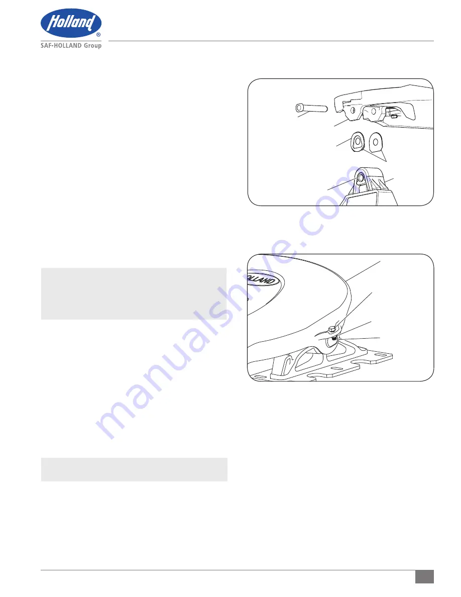
Figure 31
Figure 32
Top Plate Installation
3. Line up the holes of a new metal bracket shim and
rubber washer between the outside ear of the fifth
wheel and the mounting bracket. Rubber washer must
be placed between the outside ear and the metal
bracket shim
(Figure 31)
.
4. Insert the bracket pin through the outside ear of the
fifth wheel, metal bracket shim, rubber washer, and
halfway through the mounting bracket to hold the
bracket shims in place
(Figure 31)
.
5. Repeat Steps 3-4 for the opposite side of the fifth
wheel. If needed, the fifth wheel could be pushed
from side-to-side on the brackets to create space for
the bracket shims.
6. Once the outside bracket shims are installed, line up
the holes of a new metal bracket shim between the
inside ear of the fifth wheel and the mounting bracket.
7. Complete insertion of the bracket pin through the
bracket shim and into the inside of the fifth wheel.
8. Repeat Steps 6-7 for the last remaining metal bracket
shim between the other inside ear and mounting bracket.
IMPORTANT: I
f there is NOT enough room for the rubber
washers to be installed, or when installed
the fifth wheel DOES NOT freely articulate,
remove rubber washers and install metal
bracket shims only.
9. Secure bracket pins by installing the 1/2"-20 x 1-1/4"
hex head cap screws and 1/2"-20 lock nuts
(Figure 32)
. Torque the hex head cap screws to
50-60 ft.-lbs. (68-81 N•m).
12. Top Plate Installation
(for cast mounting brackets)
1. If pocket inserts are dislodged from fifth wheel top plate,
clean pocket area of forging and apply a strip of double-
face tape in the bottom of pockets. Install pocket inserts
by pressing down into pockets
(Figure 30).
2. Using a lifting device capable of lifting 500 lbs. (227 kg),
install the fifth wheel top plate onto its mounting base.
NOTE:
Follow instructions published by lifting device
manufacturer for proper operation of lifting device.
3. Install the bracket pins through fifth wheel top plate and
mounting base and secure by installing the 1/2"-20 x 1-1/4"
hex head cap screws and 1/2"-20 lock nuts
(Figure 32)
.
Torque the hex head cap screws to 50-60 ft.-lbs. (68-81 N
•
m).
BRACKET PIN
OUTSIDE EAR
RUBBER WASHER
BRACKET SHIMS
RUBBER CUSHION
MOUNTING
BRACKET
TOP PLATE
1/2"-20 LOCK NUT
BRACKET PIN
1/2"-20 x 1-1/4"
HEX HEAD
CAP SCREW


