Keep the manual for future reference – For more informations visit www.saerelettropompe.com
37
The auxiliary devices that can be supplied are:
PTC thermistor
-
On request for frame size 200 and below, standard from frame size 225 and above.
-
Terminals:
-
Frame size up to 200: free terminals inside the motor terminal box.
-
Frame size 225, 250, 280: two-terminal terminal block inside the motor terminal box.
-
Control device to be provided inside the electrical control panel, borne by the purchaser or supplied upon request.
PT100 temperature probe
-
Supplied on request, available for winding and/or bearings.
-
Terminals:
-
Frame size up to 132: free terminals inside the motor terminal box.
-
Frame size starting from 160 and higher: Three-terminal terminal block for each probe supplied, located in the motor
terminal box or in a special auxiliary box.
-
Control device to be provided inside the electrical control panel, borne by the purchaser or supplied upon request.
Anticondensation heater
-
Supplied on request.
-
Free terminals inside the motor terminal box.
-
Power supply voltage to be specified when ordering.
ATTENTION!
ü
Make sure that the anti-condensation heaters are not powered with the motor running.
Vibration sensors for bearings
-
Available on request. Type, method of connection and control to be agreed when ordering.
For more information, refer to the specific documentation of the auxiliary device.
5.6 CHECKS ON THE ELECTRICAL SYSTEM
·
Check the compliance of the electrical system with the CEI EN 60204-1 standards and local regulations in force.
For US market: Verify that the electrical system complies with the US National Electrical Code (NEC) and any
other local and national standards or ordinances.
·
Check in particular:
ü
The existence of the electrical grounding line.
For US market: refer to the most recent article 250 (Grounding) of the United States National
Electrical Code (NEC) for more information;
ü
the presence of a supply disconnecting (isolation) device according to EN 60947. The selection and
installation of the device are the responsibility of the installer. The presence of an omni-polar switch
disconnector that can disconnect all the feeding cables to insulate the motor in case of malfunction
or small maintenance operations (the disconnection device from the supply mains must be over-
voltage III category) is recommended.
ü
The presence of a high sensitivity differential switch (0.03 A): the differential adjustment must be on
the lowest possible values, compatibly with the correct operation of the equipment;
ü
the presence of an emergency stop button.
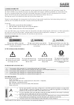
ATTENTION!
ü
Check the presence and correct installation of the necessary auxiliary connections.
ü
They must also be present:
ü
a thermal protection device adjusted on a maximum absorbed current not higher than 5% the current
ü
stated in the label and with an operating time lower than 30 seconds.
ü
A device of minimum voltage that protects from voltage drops.
ü
A device for protection against lightning surges or cause by the operation for the protection of the
motor.
ü
A device for checking the phase sequence.
ü
Check that the power cables are suitable for the application, have an adequate section so as not to cause a
voltage drop of more than 3% and not to exceed the maximum operating temperature.
5.7 CHECKS ON THE MOTOR/GROUP
Before installing the motor:


