


176.12
.A03
7 - 3
ADJUSTMENTS
7
Revision 01 Date 14.11.2001
E
G
F
D
H
C
I
A
H
C
T0416/1
T0416/2
T2440
T2441
A
Screw
B
Screw
C
Screw
D
Screw
E
Tool
F
Hole
G
Cutter
H
Clamp nut
I
Ring nut
L
Cam
M Roller
N
Extruder nozzle
O
Screw
P
Runner
Q
Cutting clearance
R
Comparator
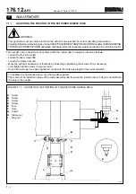
FIGURE 7.1.2 - EXTRUDER NOZZLE HEIGHT ADJUSTMENT
7.1.2
EXTRUDER NOZZLE HEIGHT ADJUSTMENT
E0004P
WARNING!
This operation must be carried out when the extruder has reached its correct operating temperature.
Carefully follow the instructions given in the SAFETY EQUIPMENT AND PRECAUTIONS chapter, RISKS
DERIVING FROM HIGH TEMPERATURES paragraph and always take the necessary safety precautions to avoid
being burnt.
To adjust the position of the extruder nozzle proceed as directed below:
- Use the handwheel to run the machine until the cutter (G) is brought over the extruder nozzle hole (N).
- Place the comparator (R) on the block which holds the roller (M).
- Loosen the screws (B & D) on the ring nut (I).
- Loosen the screw (O) and completely lower the runner (P).
- Turn the ring nut (I) until the extruder nozzle (N) is brought into contact with the cutter (G). The pointer of the instrument
(R) will begin to move when the two parts begin to touch each other.
- Observing the instrument (R), turn the ring nut (I) to raise the nozzle (N) by 0.2 mm. Allow the roller (M) to move the
same distance away from the cam raceway (L).
- Tighten the screws (D & B) which fix the ring nut and mount respectively.
- Adjust the clearance of the cutter (see relevant paragraph).
B
R
M
0,2
L
G
Q
P
N
O
Summary of Contents for PMV 224
Page 2: ...TABLE OF CONTENTS 176 12 A03 0 2 Revision 01 Date 14 11 2001 ...
Page 4: ...TABLE OF CONTENTS 176 12 A03 0 4 Revision 01 Date 14 11 2001 ...
Page 34: ...2 22 176 12 A03 Revision 01 Date 14 11 2001 2 MAIN FEATURES ...
Page 42: ...3 8 176 12 A03 Revision 01 Date 14 11 2001 SAFETY EQUIPMENT AND PRECAUTIONS 3 ...
Page 64: ...5 4 5 START UP 176 12 A03 Revision 01 Date 14 11 2001 ...
Page 70: ...6 6 176 12 A03 Revision 01 Date 14 11 2001 6 OPERATING INSTRUCTIONS ...
Page 126: ...8 30 176 12 A03 Revision 01 Date 14 11 2001 8 MAINTENANCE ...
Page 128: ...9 2 176 12 A03 Revision 01 Date 14 11 2001 9 DECOMMISSIONING ...


