


6 - 5
176.12
.A03
Revision 01 Date 14.11.2001
OPERATING INSTRUCTIONS
6
6.2
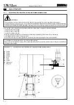
WORK CYCLE
FIGURE 6.2 - WORK CYCLE
1
The caps are fed continuously (facing the right way up and in lines) to the insertion drum.
2
Insertion drum: sprue cut (if present in the cap); pellet placed in caps
3
Plastic compound feed hopper
4
Plastic compound extruder
5
First transfer unit
6
Forming unit: the liners are formed inside the caps
7
Second transfer unit and cap cooling
8
Quality control unit: caps checked with a pneumatic/mechanical system
9
Discharge unit
10 Exit channel and cap counter
1st Rej. Caps rejected because defects detected by vision system (if installed).
2nd Rej. Caps rejected because of defects detected by pneumo-mechanical system and sensor that detects
double liners
2
5
3
4
6
7
8
9
10
2
°
Sc.
1
°
Sc.
1
T0601
1st Rej.
2nd Rej.
Summary of Contents for PMV 224
Page 2: ...TABLE OF CONTENTS 176 12 A03 0 2 Revision 01 Date 14 11 2001 ...
Page 4: ...TABLE OF CONTENTS 176 12 A03 0 4 Revision 01 Date 14 11 2001 ...
Page 34: ...2 22 176 12 A03 Revision 01 Date 14 11 2001 2 MAIN FEATURES ...
Page 42: ...3 8 176 12 A03 Revision 01 Date 14 11 2001 SAFETY EQUIPMENT AND PRECAUTIONS 3 ...
Page 64: ...5 4 5 START UP 176 12 A03 Revision 01 Date 14 11 2001 ...
Page 70: ...6 6 176 12 A03 Revision 01 Date 14 11 2001 6 OPERATING INSTRUCTIONS ...
Page 126: ...8 30 176 12 A03 Revision 01 Date 14 11 2001 8 MAINTENANCE ...
Page 128: ...9 2 176 12 A03 Revision 01 Date 14 11 2001 9 DECOMMISSIONING ...


