7
GB
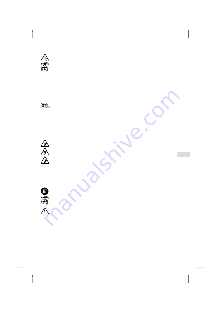
Never put your hands or feet near or under revolving parts. Always make sure that your hands or feet do not get
under the housing. Always maintain a safe distance from the ejector opening.
Stop the motor, pull the plug, check that all moving parts have come to a complete standstill:
– when leaving the machine;
– before checking the power connection;
– before you check, clean or carry out any work on the machine;
– before you eliminate jams or blockages in the ejection channel;
– when you hit a foreign body;
– if the machine starts to vibrate strangely.
•
If a foreign object has been encountered or if the machine becomes blocked, e.g. by driving onto an obstacle, a
specialist dealer must check whether parts of the machine have been damaged or deformed. Any necessary repairs
must also be carried out by an authorized specialist workshop.
•
If you notice unusually strong vibrations in your machine, you must have it checked by an authorized dealer.
Switch the engine off, and ensure that all moving parts have come to a complete standstill:
– if you have to lift or tilt the lawnmower, e.g. in order to transport it,
– when transporting the machine to and from the lawn
– when moving the machine off the lawn area;
– if the machine is left unattended for a few minutes;
– when adjusting the cutting height;
– before removing the collector bag;
– before the mulch stopper is removed.
Maintenance and storage
•
Ensure that all screws have been tightened securely and that the machine is in a safe working condition.
The ejection flap must only be opened and the grass collector or mulch stopper removed when the engine is
turned off.
Before you start mowing, always check the grass collecting equipment for wear or loss of functionality.
Before you start mowing, always check the condition and firm attachment of the cutting blade. The blade
attachment screw must always be tightened by an authorised workshop since an insulation protection test
always has to be carried out after repairs or maintenance work on insulation parts (e.g. blade screw) in
accordance with the applicable standard DIN EN 60335. A worn or damaged blade must always be replaced.
Always have the replacement, sharpening or balancing of the blade carried out by an authorised workshop,
since according to the applicable standard DIN EN 60335, an insulation test must always be carried out
following repairs or maintenance work to insulating components (e.g. blade screws).
•
For reasons of safety, always replace worn or damaged parts.
Protective gloves must be worn at all times during maintenance and cleaning work.
Maintenance and cleaning work may only be carried out with the motor switched off and mains plug
disconnected. When servicing the cutter blades note that they can be moved even when the voltage source is
switched off.
Do not clean the machine with running water or pressure cleaners. This could damage the electrical system.
For warranty and safety reasons, original replacement parts must be used at all times.
•
Notes for Switzerland:
Electric appliances must only be operated if a residual current operated device with a maximum breaking current of 30
mA is also integrated into the circuit.
•
Notes for Austria:
The socket coupler of the connecting cable must be splashproof.
Summary of Contents for 36-EL
Page 5: ......
Page 6: ...A1 E1 B1 Q1 R1 S1...
Page 7: ...I C2 D2 A2 F M...
Page 12: ...U2 J K L O N...
Page 13: ...Q S...
Page 14: ......
Page 82: ...2 RU 1 1 2 3 4 5 6 7 8 GS 9 10 11 12 CE 13 14 2 SABO SABO SABO Maschinenfabrik GmbH...
Page 83: ...3 RU 3 DIN EN 60335...
Page 84: ...4 RU 4 SABO 5 16...
Page 85: ...5 RU H05 RN F H05 VV F DIN VDE 0282 4 3 x 1 DIN VDE 0620 230 16 30...
Page 86: ...6 RU 30 15 C 1...
Page 87: ...7 RU 3 3 11 4 6 2 12 H 05 RN F H05 VV F DIN VDE 0282 4 DIN EN 60335...
Page 88: ...8 RU DIN EN 60335 DIN EN 60335 30 6 1 2 3 4 5 6 7 8 9 10 11 12...
Page 89: ...9 RU 7 A1 E1 B1 Z A1 E1 B1 B1 E1 B1 Q1 R1 S1 Q1 Q1 R1 R1 1 S1 I 3...
Page 91: ...11 RU 5 1 2 3 4 5 6 10 F 3 11 3 12 3 1 S1 J K J K L...
Page 92: ...12 RU 13 3 30 15 3 DIN EN 60335 10 32 32 BImSch V M 10 14...
Page 93: ...13 RU DIN EN 60335 10 1 3 1 3 1 2...
Page 94: ...14 RU U2 S1 U2 S1 14 10 50 1 15 3 O...
Page 95: ...15 RU A1 Z A1 N N Q DIN EN 60335 1 Q 30...
Page 96: ...16 RU DIN EN 60335 S 50 16 5 C2 I Q I...
Page 97: ...17 RU J K L I 1 3 10 I U2 S1 I I...
Page 98: ......


