background image

25

B2-GRQ-OpGuide-v9-031020.pmd

S

ECTION

 E

IGHT

:  U

SING

 GRQ2 R

EMOTE

 S

OFTWARE

8.2.5.1.  Setting FBX Filters with Graphi-Q Remote Software

The Remote Software offers an additional method for setting FBX filters.  The new software option is
called 

Auto Setup Mode

. See 

Section 6.4.1

 for more information about feedback filter and terminology.

Also please read 

Section 6.4

 for a more complete discussion of Setup Mode.

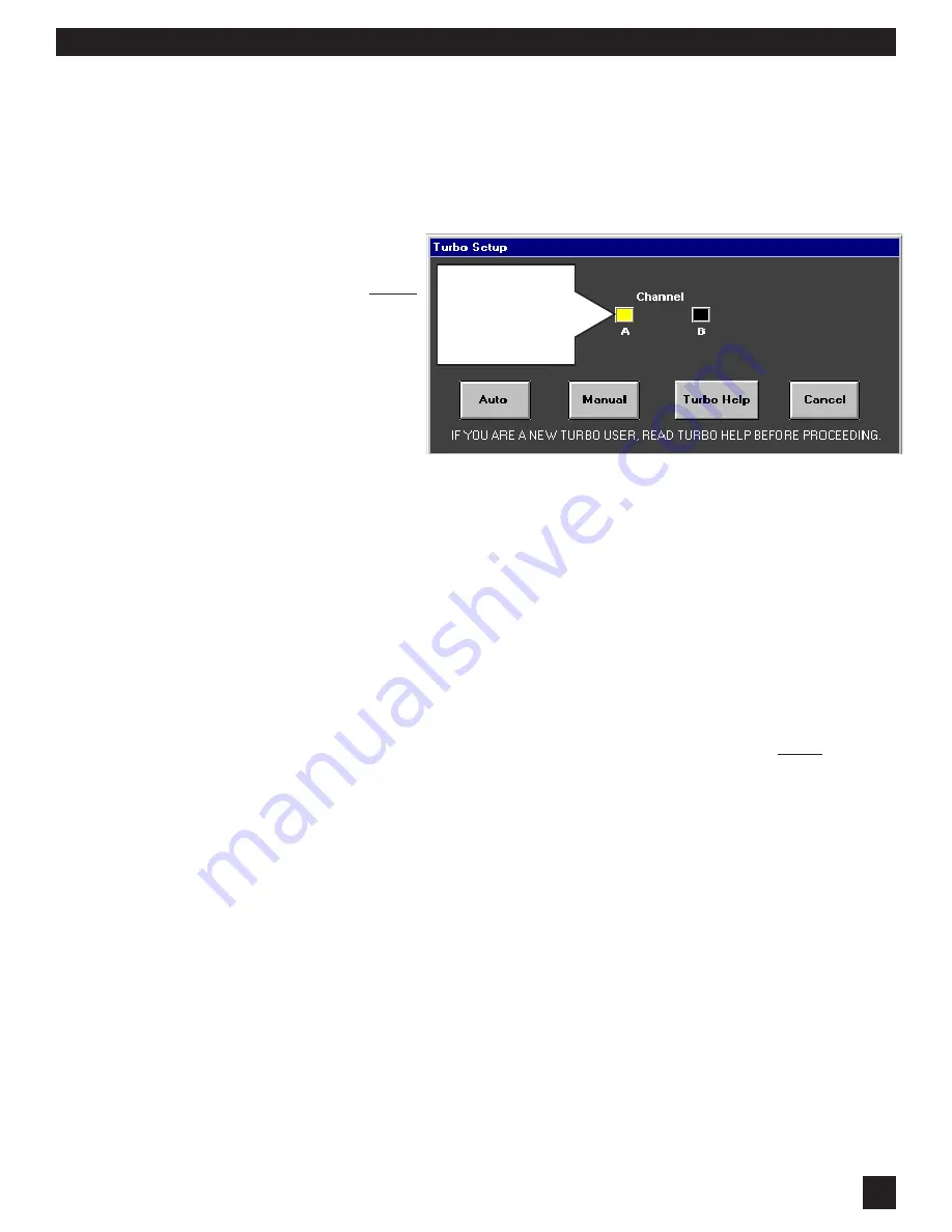
For Remote Control operation, Manual or Auto Setup Modes can only be accessed by resetting all FBX
filters in one or both channels (for two channel units). If you have a 2-channel unit, and have reset filters
in both channels, you will be asked to select the channel for setting FBX filters in Setup Mode.

NOTE: The FBX filters will not
set on single channel units if
you have the B output channel
FBX filters in bypass 

before

setup.

Once you are familiar with Setup
options, you may move for-
ward by clicking the appropri-
ate selection. If you are unfa-
miliar with Setup Mode opera-
tion, click 

Setup Help

.

Using Auto Setup: 

 Before selecting 

Auto Mode

, make sure all your microphones are positioned, and

turned up to the approximate correct gain setting for each input, while the master gain on your mixer is
turned down.  Raise the master gain slowly (only for the appropriate channel for a 2-channel system) until
you hear the first hint of feedback, then click on 

Auto 

.  At this point, the Graphi-Q2 will take over, and

slowly raise its output gain, setting FBX filters sequentially as the gain increases.  You will see the filters
being set in the FBX/Parametrics screen (the response curve will change and the actual frequency value
of the feedback will be displayed) and a display of the amount of gain increase.  Feedback will occur at
a very low volume.  Setup mode will exit, and the gain will be dropped slightly (for a safety margin), when
all fixed filters and the first dynamic FBX filter have been set, or when Setup is turned off by clicking on
the 

Cancel Setup 

button.

For two-channel systems, 

Auto Setup

  will prompt you to perform the same setup for the second channel,

or exit to normal operation. For models GRQ3121 and GRQ3121-S, 

Auto Setup

  will set the same filters

simultaneously for both A and B outputs, and will show the B output FBX/parametric screen during setup.
You cannot set FBX filters in Output A if FBX/Parametric for Output B is bypassed before setup. Set
filters first, then bypass B.

Using Manual Setup


:

  If you select 

Manual Mode

, the master gain must be raised manually (again,

we recommend only one channel at a time for two-channel units).  Raise the gain until the system is on
the verge of feedback, then walk around the stage with a microphone until you find a position that excites
feedback.  Slowly raise the gain to cause enough feedback to set an FBX filter.  Repeat the process until
all of the Fixed filters and one Dynamic FBX filter are set.  Then lower the gain slightly.  During Manual
Setup  operation, feedback will be kept to a low volume, and you will be able to see filters setting on both
the curve display, and in the FBX/Parametric screen.  Manual Setup  Mode will exit when either the first
dynamic FBX filter is set, or when you click on the Cancel Setup  button.  You’ll be prompted when Manual
Setup  is exiting, and you may need to adjust system gain when Setup  is releasing and no longer limiting
feedback to a lower level (setup only).  Be aware of the potential for any ringing feedback to briefly rise
in volume.

8.2.5.2.  Gain Structure and Manual Setup

If your power amplifier gain is low, Manual Setup Mode may not work well. The level of feedback is
compressed during Manual Setup, and the combination of compressed output and low amplifier gain may
keep feedback below its threshold. Raise the amplifier gain to correct this. This situation cannot occur
in Auto Setup Mode.

For two-channel systems, 

Manual 

Setup will allow you the choice of either performing the same  setup

NOTE:

 Channel A & B

boxes appear only
when GRQ3122 or
GRQ3122-S models
are connected.

Summary of Contents for GRAPHI-Q2

Page 1: ...mpressor Limiter with controls for ratio threshold and gain attack release and knee adjustable with remote Digital Delay with up to 1 second delay adjustable in 20 microsecond increments Bypass dedica...

Page 2: ...E MARKING We the Manufacturer SABINE INC 13301 NW US HIGHWAY 441 ALACHUA FLORIDA USA declare that the product EQUALIZER SABINE MODEL GRQ3100 Is in conformity with Council Directive 73 23 EEC and 89 33...

Page 3: ...Y SOFTWARE 18 6 9 FRONT PANEL CONTROL OPTIONS 18 Section Seven GRQ2 Remote Software Installation 19 7 1 SYSTEM REQUIREMENTS AND RECOMMENDATIONS 19 7 2 CONNECTIONS 19 7 3 INSTALLING THE SOFTWARE 20 Sec...

Page 4: ...but also offer an expanded range of adjustment and ease of storage and recall that are much more difficult to achieve with analog technology And with the Sabine FBX algorithm one of the most serious...

Page 5: ...LESS FILTER DRIFT Analog circuits rely on components that vary as they age and or are subjected to different ambient temperatures This variation can in turn cause analog filters to drift from their or...

Page 6: ...cut for 31 specific frequencies High Low Cut Filters Input signal gain reduction indicators Digital Delay up down controls EQ range Press up down buttons simulta neously to toggle EQ range between 6...

Page 7: ...122 Front Panel G G G G GR R R R RQ3 Q3 Q3 Q3 Q3122 Bac 122 Bac 122 Bac 122 Bac 122 Back Panel k Panel k Panel k Panel k Panel G G G G GR R R R RQ3 Q3 Q3 Q3 Q3122 S Bac 122 S Bac 122 S Bac 122 S Bac 1...

Page 8: ...8 Section Four Block Diagram Internal Signal Path SECTION FOUR BLOCK DIAGRAM INTERNAL SIGNAL PATH...

Page 9: ...g console and the input to a power amplifier In this configuration the GRQ2 can provide all your system processing including delay and crossover A typical configuration will look like this This config...

Page 10: ...label them differently When in doubt consult the manual of the console manufacturer 5 4 USE AT A MIXER INSERT POINT The Graphi Q2 may also be used at a mixer insert point either for a single input ch...

Page 11: ...and delay settings can be unique on each output 5 6 WHAT NOT TO DO The Graphi Q2 should NOT be used in the following configurations 1 Do NOT plug a microphone directly into the Graphi Q2 back panel Th...

Page 12: ...TROLS Please make note of the default front panel control protocols that apply when setting graphic EQ FBX filters compression delay and output level for the two outputs of the single input Graphi Q2...

Page 13: ...phic EQ sliders For the LOW CUT FILTER the Graphi Q2 will attenuate frequencies at and below your knob setting with a slope of 12 dB per octave For the HIGH CUT FILTER frequencies at and above the kno...

Page 14: ...tions thereof of a filter including graphic EQ filters parametric filters and FBX filters More specifically width is defined by determining the outer frequencies surrounding the filter center point th...

Page 15: ...arespecifictoeachchannel of your sound system STEP ONE EQUIPMENT SETUP Set up your sound system and position all the speakers and microphones you anticipate using When possible avoid placing microphon...

Page 16: ...back a second time and an earlier filter will notch more deeply Whenthishappens theoriginalLEDindicatingthisfrequencywillblink showingittobethemostrecently active filter Repeat this procedure until on...

Page 17: ...for usingtheGraphi Q2RemoteControlSoftwareCompressor Limitercontrol 6 6 DIGITAL DELAY CONTROLS 6 6 1 Front Panel Control DIGITAL DELAY controls are located to the right of the COMPRESSOR controls You...

Page 18: ...er settings choose Global Parameters F5 key from the MAIN MENU or Global fromwithintheFBX Parametricscreen Youmaychangeanyvaluewithintheindicatedranges and your new settings will be used as new defaul...

Page 19: ...ted user to load settings No cost future proof upgrading Your Graphi Q2 can be updated via a simple connection to the Sabinewebsite www Sabine com wheneverfirmwareand orsoftwareupgradesareannounced Al...

Page 20: ...led GRQRemote NOTE forupdatingsoftwareorre flashingfirmware seesection8 10 UpgradingGraphi Q2Firmware andSoftware TECH TIP PC can t find Graphi Q2 Try these tips if you are having difficulty con necti...

Page 21: ...your computer you can set up two distinct networks of Graphi Qs each consisting of up to eight units NOTE one COM port chain cannot communicate directly to another only within its own chain Double cli...

Page 22: ...for a description of the control protocols for GRQ functions 8 2 1 Graphic Equalizer Changing EQ slider settings can be accomplished in three ways 1 Click and drag the desired EQ slider with the mouse...

Page 23: ...type a value or 3 Adjust the gain knob in the Compressor Limiter section of the Remote Software main screen Compressor Gain and Output Level Controls are redundant and will change together 8 2 5 FBX F...

Page 24: ...obal Parameter Link Indicator Important Note on Equipment Power on Sequencing and Feedback Suppression The Graphi Q2 is similar to a computer in that it requires several seconds to boot up and become...

Page 25: ...first dynamic FBX filter have been set or when Setup is turned off by clicking on the Cancel Setup button Fortwo channelsystems AutoSetup willpromptyoutoperformthesamesetupforthesecondchannel orexitto...

Page 26: ...The A output is for the low frequency band and the B output is for the high frequency band GRQ3122 or GRQ3122 S These are 2x2 units When using the crossover use only the A channel input Engagingthecr...

Page 27: ...channels will be the ratio applied to both signal paths as well Note that stereo compression is distinct from linked compressor settings See Section 8 3 2 5 CompressorLinkingOptionsforGRQ3122andGRQ31...

Page 28: ...ass controls are located at the bottom of the main screen and are activated by clicking the appropriate bypass boxes Active front panel units will display the appropriate bypass status as well The Rem...

Page 29: ...meters for ABSOLUTELY LINKED cells will be copied to the identical setting The first cell you choose for your ABSOLUTE LINK group will be the source value forcopying andwillbehighlightedwitharedcolor...

Page 30: ...AlllinkingthatinvolvestheA channelforsuchunits will automatically be applied to the B channel as well 8 3 2 2 Bypass Linking Bypass ActivestatusforallparametersisNOTincludedunderthecontroloflinkedcell...

Page 31: ...ort in the other screen 1 In the Link Table enter the letter S in the appropriate channel boxes and click Apply 2 IntheCompressor Limiterscreen youmaytoggletheboxbelowtheCLOSEbuttontoengageeither True...

Page 32: ...6 to 12 dB or vice versa will also change the scale for all linked units graphic EQ settings For REL LINK all scales will not change when one unit s scale is altered Instead all changes made will be i...

Page 33: ...f how controls are linked for a multiple unit Graphi Q2 system Simply select PRINT from within the link table If you are out in the field and not attached to a printer you can use the Off Line Edit De...

Page 34: ...Control screens will display these manual adjustments but remote control will be disabled The Curve Display on your monitor will indicate Preset 1 Front Panel in Control 2 Any adjustments made manuall...

Page 35: ...tputs mostoftheparametersettingscanonlybesettoidenticalvalues forbothoutputs Fortheseparameters thesettingforchannelAoftheGRQ3122 savedpresetwillalso be copied to the B output for the GRQ3121 destinat...

Page 36: ...f Line Editing FromtheGraphi Q2WelcomeScreen Section8 1 thatappearsuponlaunchingtheprogram youmay click on the Off Line Edit Demo button instead of connecting to actual Graphi Q This will open the sof...

Page 37: ...e Graphi Q should set passwords To do this open the PASSWORD screen from the Tool Bar at the top of the main screen The PASSWORD screen looks like this Click the EDIT PASSWORD box The three password b...

Page 38: ...fortheGraphi Q2 You can determine your Graphi Q2 s current firmware version by one of two methods 1 For front panel models GRQ3121 or GRQ3122 the firmware version will flash briefly in the digital del...

Page 39: ...If you re moving your sound system around and can t rebuild the room each time you move or if you re working in an environment where you ve done all you can to improve the acoustics here are a few rul...

Page 40: ...mon examples would include audio hum induced by AC electrical current 50 or 60 Hz plus harmonic multiples of those frequencies or acoustical feedback that arises when amplified sound is directed back...

Page 41: ...ers the more extreme the boost or cut the more ripple peaks or dips centered at the EQ slider frequencies there will be in the resultant system frequency response VARY LEVEL AND LOCATION If you re mak...

Page 42: ...requencyspeakersinmovietheatersbyfeeding a sharp click through the system They moved the speakers until they could only hear a single sharp click coming from both speakers You can use this same method...

Page 43: ...ine to form visibleinterferencepatterns In some places the wave crests and troughs are in phase so theycombinedtomakealarger wave Inotherplacesthecrests are out of phase so the crest of one wave sourc...

Page 44: ...in every live sound system and they cannot be corrected with equalization Fortunately most comb filter problems can be reduced to a minimum by synchronizing the signals and reducing the amplitude of...

Page 45: ...f the signals from the under balcony speakers arrive within 10 msec of the signals from the center cluster Therefore we should set the delay to 65 69 msec You can allow a little more reverberation for...

Page 46: ...ffect to the second performer by placing the Graphi Q in the mixer s channel insert point and adding a 25 msec delay Certainly taking advantage of the Precedence Effect is not as obvious to the audien...

Page 47: ...ften added to the entire audio mix both in live sound and recording to increase its perceived loudness Mix consistency For expressive instruments or vocals which may have a large dynamic range compres...

Page 48: ...gain change at the input level for signal levels that rise above the threshold Acompressionratioof4 1iseffectivelyalimiter nomatterhowmuch loudertheinputrisesabovethethreshold theoutputlevelremainsun...

Page 49: ...h the signal is compressed once the gain exceeds the threshold Attack is generally set to a very quick response and can be varied from 1 to 99 msec Release Release sets the speed with which the output...

Page 50: ...catches all hits medium attack quick release gain makeup boosted slightly soft knee BASS GUITAR Bass players use a variety of tech niques often in the same song that can benefit from compression Comp...

Page 51: ...aphi Qpatchedinan effects or auxiliary loop you will only catch the feedback in the effects loop and not the mixer input channel Or you may have usedupalltheavailableFBXfilters leavingnoadditionalfilt...

Page 52: ...ROL DOESN T WORK SIGNAL LOSES GAIN GOING THROUGHGraphi Q2 PARAMETRIC FILTERS DO NOT LINK REMOTE SOFTWARE SCREEN DISTORTED LETTERS DO NOT FIT CORRECTLY The FBX filters will not set on single channel un...

Page 53: ...l GRQ Remote RS 232 Re mote switching GRQ3122 S GRQ3121 S GRQRemote RS 232 Remoteswitch ing SAVE RECALL CONFIGURATIONS 20 user defined 1 factory default 1 most recent configuration power down save 1 f...

Page 54: ...h the receiver is connected Consult the dealer or an experienced radio TV technician for help Canadian Compliance Statement This digital apparatus does not exceed the Class B limits for radio noise em...

Page 55: ...rectly related to the cause of action Such purchase price will be that in effect for the specific product when the cause of action arose This limitation of liability will not apply to claims for perso...

Page 56: ...Contact Closure 35 Linking FBX Filters 28 Linking Front Panel Control 31 Linking Parametric Filters 29 Linking Resetting Parameters 31 Linking FBX Parametric conflicts 52 Linking No Absolute Relative...

Reviews: