


32
EN
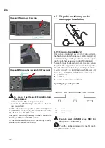
To carry out the electrical connections to
the T-MB control, remove the insulated pro-
tection device from the clamp.
Once the electrical connections were done,
replace the protection as in the picture 14.6.
Reassemble the front part of the control,
placing the two flaps located on the lower
side.
Then close the control, by making the upper
flap click.
14.6
14.2 Control Electrical Connections
The control panel must be wired to the power board
located inside the electrical compartment of the unit,
complying with the correspondence of the common
numbering to both boards.
Use 3 conductors with 0.5 mm2 section.
The connection wirings must not exceed 20
metres in length.
Respect the right wiring sequences.
5
6
7
5
6
7
Main Board
T-MB
4
3
2
1
Main Board
T-MB
14.2.1 DIP switches setting
DEFAULT
Set dIP can be used to modify the functions per-
formed by the controller (as shown in the table 14.1).
Summary of Contents for QCV-MB
Page 3: ...3 IT da p 5 EN from p 23 ...
Page 59: ......


