7
PLANNED MAINTENANCE
—QUARTERLY INSPECTION
Photo Eye Inspection
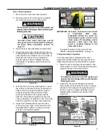
Inspect the photo eye mounting brackets and photo
eyes for visible damage or misalignment. Verify that
the photo eyes operate as described below:
Personnel and objects should not be in the path of
the door when the following inspection is
performed. If the photo eyes are not working
properly, the door could
strike an individual
or object in its path.
1. Open the door to the fully open position by
pressing the open
(▲) key located on the Rytec
System 4 Drive & Control Panel.
2. Place an object between the photo eyes to
interrupt the light beam between the photo eye
transmitter and receiver.
3. Press the close
(▼) key on the Rytec System 4
Drive & Control Panel. The door should not move
or close at all.
4. Remove the object and cycle the door to verify
that the front set of eyes is working properly.
5. If the photo eyes on the door front are not
working properly, the photo eyes may be dirty.
Clean the lens of each eye as required, using
window cleaner and a clean, soft cloth. If this
does not resolve the problem, see “PHOTO EYE
ADJUSTMENT-ALIGNMENT
” on page 17 for
adjustment procedures.
Refer to “PHOTO EYES” on page 4 for additional
information on how the photo eyes operate.
QUARTERLY INSPECTION
Electrical Inspection
CONTROL PANEL, ENCODER, AND MOTOR
WIRING
The disconnect must be in the OFF position and
properly locked and tagged before performing the
following procedure.
1. Inspect electrical connections to the power drive
assembly and encoder assembly.
2. Inspect control panel wiring. See Rytec System 4
Drive & Control Installation & Owner’s Manual for
control panel inspection procedure.
UPPER JUNCTION BOX
NOTE: The upper junction box is an optional item
that may have been installed during the
installation of your door. If an upper junc-
tion box was installed, it was most likely
mounted on the wall, just above the control
panel. If your door has an upper junction
box, it must be inspected.
1. Move the door to the fully closed position.
2. Remove power to the control panel by placing
the fused disconnect in the OFF position.
The disconnect must be in the OFF position and
properly locked and tagged before performing the
following procedure.
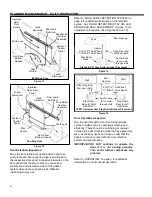
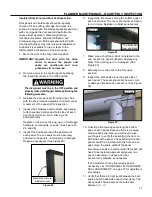
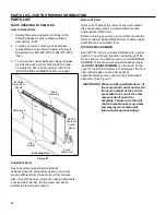
3. Remove the cover from the upper junction box
located above the door opening. (See Figure 17)
4. Inspect all electrical connections in the upper
junction box. All connections must be tightly
secured.
5. Check for pinched, kinked, cracked, or damaged
wires and insulation. Repair or replace wires as
needed.
6. If the door is configured with the optional defrost
system (heat tapes), inspect all associated
electrical wiring and connections. Repair or
replace wires as needed.
Figure 17
7. Replace the cover.
8. Apply power to the door.
Rework this
Figure
Bi-Parting Door Shown
One-Way Door Is Similar
System 4
Control
Panel
Upper
Junction
Box
Fused
Disconnect

