background image

PARTS LIST

—SINGLE SLIDE DOOR PANEL ASSEMBLY 

34 

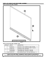
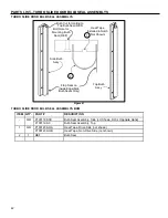
SINGLE SLIDE DOOR PANEL ASSEMBLY 


Figure 53 

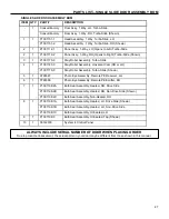
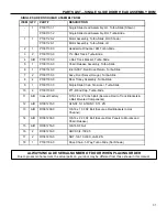
SINGLE SLIDE DOOR PANEL ASSEMBLY BOM 


ITEM  QTY.  PART # 

DESCRIPTION 

P1091112-1 

Panel Assy, 1-Way, LH (Opens to Left) Turbo-Slide 

P1091112-2 

Panel Assy, 1-Way, RH (Opens to Right) Turbo-Slide 

P1091113-0 

Door Panel, 1-Way, Turbo-Slide 

P1091196-0A 

Panel Bottom Seal, 1-Way, R17, Turbo-Slide 

P1091196-0B 

Panel Bottom Seal, 1-Way, R25, Turbo-Slide 

A/R 

P1091118-0 

Manual Release Handle, Turbo-Slide (Standard qty = 1) 

Single Slide Door Panel Assembly


ALWAYS INCLUDE SERIAL NUMBER OF DOOR WHEN PLACING ORDER 

Due to product enhancement, the actual parts on your door may be different from those shown in this manual. 


Summary of Contents for Turbo-Slide

Page 1: ...ne 262 677 9046 Fax 262 677 2058 Rytec Website www rytecdoors com Rytec On line store www rytecparts com Rytec E mail helpdesk rytecdoors com Parts E mail parts rytecdoors com Revision AA 2017 09 13 R...

Page 2: ......

Page 3: ...their agents access to Buyer s premises for the purpose of repairing or replacing the Product or y return of the Product to the Seller f o b Seller s factory Original Buyer This Limited Warranty is ma...

Page 4: ...all not be construed as an express warranty Any suggestions by the Seller or the Seller s agents regarding the use application or suitability of the Product shall not be construed as an express warran...

Page 5: ...ion 5 Door Retention Inspection 6 Door Operation Inspection 6 Photo Eye Inspection 7 QUARTERLY INSPECTION 7 Electrical Inspection 7 CONTROL PANEL ENCODER AND MOTOR WIRING 7 UPPER JUNCTION BOX 7 Mounti...

Page 6: ...BLY ALIGNMENT AND ADJUSTMENT 19 PARTS LIST 22 PARTS ORDERING INFORMATION 22 How to Order Parts 22 Substitute Parts 22 Return of Parts 22 DOOR SERIAL NUMBER 22 RYTEC TECHNCIAL KNOWLEDGE CENTER 23 RYTEC...

Page 7: ...EMBLY BOM 37 TURBO SLIDE DOOR SWIVEL HANGER ASSEMBLY 38 TURBO SLIDE DOOR SWIVEL HANGER ASSEMBLY BOM 38 TURBO SLIDE DOOR TROLLEY ASSEMBLY 39 TURBO SLIDE DOOR TROLLEY ASSEMBLY BOM 39 TURBO SLIDE STAY RO...

Page 8: ......

Page 9: ...d to alert the reader to potentially hazardous situations or situations where additional information to successfully perform the procedure is presented WARNING is used to indicate the potential for pe...

Page 10: ...the door Left and right are determined when facing viewing the front side of the door This is the side that the door assembly is mounted on the same side the head assembly is on All views shown on thi...

Page 11: ...tension the drive chain The door panel s are connected to the drive chain via the chain release mechanism and hang from trolleys The trolleys roll along tracks in the head assembly to move the door pa...

Page 12: ...rd radio control etc the door will remain open until it is closed by a non automatic activator If the door was opened by an automatic activator floor loop motion detector etc the door will close autom...

Page 13: ...nted to each Bi Parting panel leading edge and form a seal between the panels when the door is closed To adjust the door panel seals follow the procedures in the Adjustments section PLANNED MAINTENANC...

Page 14: ...s remain in contact with the door retention system and seal properly IMPORTANT DO NOT continue to operate the door if it is not running properly This could further complicate any problem Refer to OPER...

Page 15: ...The disconnect must be in the OFF position and properly locked and tagged before performing the following procedure 1 Inspect electrical connections to the power drive assembly and encoder assembly 2...

Page 16: ...missing hardware as necessary See Figure 20 Figure 20 Door Retention Inspection 1 Check all mounting hardware associated with the stay roller door retention system Check that it is properly placed Im...

Page 17: ...to the head assembly Tighten or replace any loose missing or damaged hardware Figure 23 Figure 24 IMPORTANT Excessive chain tension can result in accelerated chain wear Inadequate tension can cause th...

Page 18: ...e door to the fully closed position Then remove power to the control panel by placing the fused disconnect in the OFF position The disconnect must be in the OFF position and properly locked and tagged...

Page 19: ...spect the end seal around the perimeter of each panel The end seals must be securely adhered to the panels not cracked or damaged Repair as necessary See Figure 28 Figure 28 6 Inspect the floor sweep...

Page 20: ...a petroleum based solvent to clean the rollers or the track they travel along otherwise damage to the rollers could result 1 Inspect the panels and seals for dirt and grime Clean as required using an...

Page 21: ...return to service Chain Release Mechanism Inspection The Chain Release Mechanism Assembly allows door panel detachment reattachment to the drive chain When detached from the drive chain door panel s m...

Page 22: ...his will vary with the door size environmental conditions etc The tensioner should have a gap between the housing and bottom of the banana chain glide See Figures 34 and 35 Figure 34 Figure 35 4 Once...

Page 23: ...m of the trolley carriage and torqued to 15 Ft lbs Failure to do this will allow the trolley bolt to spin loosen which lowers the door and eventually causes the door to drag and excessive sweep seal w...

Page 24: ...ers must be aligned See Figure 38 6 If any door seal adjustment is required on the top of the door loosen the screws securing the door panel to the swivel hanger plate at the top of the door opening T...

Page 25: ...r opening face and head assembly The door panels must be level and aligned per DOOR PANEL ALIGNMENT AND ADJUSTMENT on page 14 and Top Head Door Bulb Seal Adjustment on page 16 DOOR PANEL FLOOR SWEEP S...

Page 26: ...es are properly aligned Placing your hand in front of the receiver breaks the light path and should cause the yellow light to go out Removing your hand from the light path should cause the yellow ligh...

Page 27: ...place and seal properly against the floor Make any necessary adjustments Figure 44 CHAIN RELEASE ASSEMBLY ALIGNMENT AND ADJUSTMENT The chain release assembly will occasionally need adjustment as the c...

Page 28: ...attach the Manual Chain Release Cable around the 2 bolts on the Chain Release Assembly Bracket pivot arm as shown so it is taught Torque the bolts to approximately 4 ft lbs Test the Manual Chain Relea...

Page 29: ...21 NOTES...

Page 30: ...n of any parts unless they are accompanied by a Return Merchandise Authorization RMA form Before returning any parts you must first contact the Rytec Customer Support Department to obtain return autho...

Page 31: ...k routinely ship the same day The account is strictly for the account holder All ship to bill to and ordering information is the responsibility of the account holder Currently over one hundred Rytec p...

Page 32: ...PARTS LIST BI PARTING DOOR ASSEMBLY 24 BI PARTING DOOR ASSEMBLY Figure 48 1 2 3 4 6 7 8 9 10 Bi Parting Door 5...

Page 33: ...7 Photo Eye Assembly Remote PE Receiver LH 6 1 0799368 Photo Eye Assembly Remote PE Emitter RH 7 1 P1091198 1A Bulb Seal Assembly Heated LH Drive Side P1091198 1B Bulb Seal Assembly Heated LH Non Driv...

Page 34: ...PARTS LIST SINGLE SLIDE DOOR ASSEMBLY 26 SINGLE SLIDE DOOR ASSEMBLY Figure 49 1 2 3 4 6 5 8 7 9 10 Single Sliding Door...

Page 35: ...or LH P1091170 0 Stay Roller Assembly Turbo Slide Shown 5 1 0799367 Photo Eye Assembly Remote PE Receiver LH 6 1 0799368 Photo Eye Assembly Remote PE Emitter RH 7 1 P1091198 2A Bulb Seal Assembly Heat...

Page 36: ...TING DOOR HEAD ASSEMBLY 28 BI PARTING DOOR HEAD ASSEMBLY Figure 50 2 7 3 4 6 1 8 9 12 Bi Parting Door Head Assembly 5 10 11 13 16 Detail A Detail B Detail C See Detail A 17 15 18 See Detail C 14 16 Se...

Page 37: ...150 0 Assy Door Swivel Hanger Turbo Slide 9 4 P1091160 0 Door Trolley Assembly Turbo Slide 10 1 P1091107 0 Single Slide Chain Tensioner Turbo Slide 11 2 P1091108 0 F71 R End Cap Turbo Slide 12 A R Con...

Page 38: ...SLIDE DOOR HEAD ASSEMBLY 30 SINGLE SLIDE DOOR HEAD ASSEMBLY Figure 51 2 6 3 4 9 1 7 8 11 Single Slide Door Head Assembly 5 10 12 Detail A Detail B Detail C See Detail A 16 14 17 See Detail C 13 15 See...

Page 39: ...Hanger Turbo Slide 8 2 P1091160 0 Door Trolley Assembly Turbo Slide 9 1 P1091107 0 Single Slide Chain Tensioner Turbo Slide 10 2 P1091108 0 F71 R End Cap Turbo Slide 11 A R Consult Factory 5 16 18 x C...

Page 40: ...PARTS LIST BI PARTING DOOR PANEL ASSEMBLY 32 BI PARTING DOOR PANEL ASSEMBLY Figure 52 7 4 5 6 2 Bi Parting Door Panel Assembly 3 3 1...

Page 41: ...bo Slide Constructed of items 3 5 6 7 3 1 P1091111 0 Bi Parting Door Panel Turbo Slide 4 1 P1091114 0 Assy Seal Bi Part Groove Section Turbo Slide 5 1 P1091115 0 Assy Seal Bi Part Tongue Section Turbo...

Page 42: ...pens to Right Turbo Slide 1 1 P1091113 0 Door Panel 1 Way Turbo Slide 2 1 P1091196 0A Panel Bottom Seal 1 Way R17 Turbo Slide P1091196 0B Panel Bottom Seal 1 Way R25 Turbo Slide 3 A R P1091118 0 Manua...

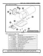
Page 43: ...wn 2 1 P1091121 0 Motor Mount Plate Turbo Slide 3 1 P1091122 0 Idler Assembly Turbo Slide 4 1 P1091123 0 Drive Sprocket Motor Turbo Slide 5 2 Consult Factory 5 16 18 x 1 25 Hex Bolt 6 2 P1091202 0 HSF...

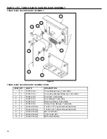
Page 44: ...ket Weldment Turbo Slide 2 1 P1091132 0 Pivot Arm Turbo Slide 3 1 P1091133 0 Door Bracket Turbo Slide 4 1 P1091134 0 Extension Spring Turbo Slide 5 1 P1091135 0 Cable Chain Release Turbo Slide 6 2 Con...

Page 45: ...Drive Turbo Slide 1 1 P1091141 0 Spring Hanger Turbo Slide 2 1 P1091142 0 Idler Sprocket Turbo Slide 3 1 P1091143 0 Tensioner L Bracket Turbo Slide 4 1 Consult Factory 13 x 1 75 Long Round Head Squar...

Page 46: ...BO SLIDE DOOR SWIVEL HANGER ASSEMBLY BOM ITEM QTY PART DESCRIPTION 1 P1091150 0 Assy Door Swivel Hanger 1 1 P1091151 0 Weldment Door Swivel Hanger Bracket Baseplate Turbo Slide 2 1 P1091152 0 Trolley...

Page 47: ...DOOR TROLLEY ASSEMBLY BOM ITEM QTY PART DESCRIPTION 1 P1091160 0 Door Trolley Assembly Turbo Slide 1 1 P1091161 0 Trolley Carriage Plate 2 4 P1091163 0 72mm 82a Wheel ABEC 7 Bearings 3 2 P1091162 0 5...

Page 48: ...TURBO SLIDE STAY ROLLER ASSEMBLY BOM ITEM QTY PART DESCRIPTION 1 P1091170 0 Stay Roller Assembly 1 1 P1091171 0 Stay Roller Base 2 1 P1091172 0 Stay Roller Wheel 3 1 Consult Factory 10 x 4 50 Long He...

Page 49: ...091181 0 Weldment Swing Arm Base Turbo Slide 2 1 P1091182 0 Swing Arm Plate Turbo Slide 3 2 Consult Factory 7 8 Hex Double Female 4 3 P1091206 0 FHSCS 1 4 20 x 5 8 5 1 P1091203 0 Nut 1 4 20 Hex Flange...

Page 50: ...l Assembly Side LH Shown RH is Opposite Hand P1091199 0 Bulb Seal Assembly Top 1 A R P1091239 OA Heat Tape Drive Side not shown P1091239 OB Heat Tape Non Drive Side not shown 2 1 REF Bulb Seal 1 Side...

Reviews: