13
INSTALLATION—PHOTO EYE
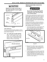
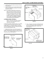
1. Install the photo eye assembly on the motor mount
side column with two 1/4-20 x 3/4-in. serrated-
flange hex screws. The mounting holes are located
approximately 40 in. from the floor. (See Figure 33.)
NOTE: Photo eyes and mounting hardware are
shipped in the small parts carton. The two
sets of photo eyes provided must both be
properly installed. (See Figure 29.)
Photo Eye
Cable
Serrated-Flange
Hex Screw
(Two Required)
A7500316
Cord
Grip
A7500315
Figure 33
Assembly
Photo Eye
Figure 34
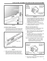
4. Install photo eye assembly on the non-drive side
column with two 1/4-20 x 3/4-in. serrated-flange
hex screws.
5. Feed photo eye cable through the cord grip.
Remove all slack in the cord between the photo eye
and grip. Tighten the cord grip.
NOTE: Mounting hardware for the second set of
photo eyes has been provided. If this hard
ware will not work for your application, any
additional required hardware becomes the
responsibility of the installer.
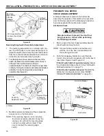
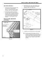
2. Install the cord grip in the side column, just below
the photo eye assembly. (See Figure 34.)
3. Feed photo eye cable through the cord grip.
Remove all slack in the cord between the photo eye
and grip. Tighten the cord grip. (See Figure 34.)
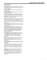
6. Mount the second photo eye assembly on the wall
adjacent to the back of the door. The photo eye
emitter and receiver are to be mounted at the same
height as the photo eye assembly on the front of the
door, but as close to the door as possible.
Testing Photo Eye Modules
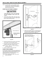
When power is on, the green light indicates the photo
eye module is powered up. When the yellow light on
the receiver module is also lit, the transmitter and
receiver modules are properly aligned.
Placing your hand in front of the receiver breaks the light
path and causes the yellow light to go out. Removing
your hand causes the yellow light to go back on.


