6
INSTALLATION—SPREADER ASSEMBLY
It is critical that the side columns are
mounted level and square to the wall and
floor, both vertically and horizontally. A
4-ft. level and carpenter’s square are
recommended for this procedure.
The use of bar clamps to secure the side
columns to the wall during installation is
recommended, as these hold the columns
securely in place, while allowing for slight
adjustments of either side column during
the installation of the head assembly.
NOTE: All necessary anchor hardware and material is
the responsibility of the door owner.
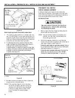
Serrated-Flange
Hex Screw
(Two on Each End)
Spreader
Extrusion
L-Shaped Support
Bracket (Mounted to
Top of Header
Extrusion)
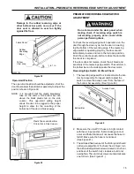
4. Once the side column is properly positioned, secure
it to the wall using the appropriate anchors. (See
“ANCHORING METHODS” on page 3.) Anchor
holes have been provided in the side column. (See
Figure 13.) DO NOT tighten the anchor hardware at
this time.
A8500004
Figure 14
Serrated-Flange Hex
Nut (Two on Each End)
NOTE: Use 1/2-in. diameter expansion shell
stud- type anchors for concrete walls or
1 / 2 - in.
diameter threaded through bolts
for brick walls and other applications
where expansion bolts are not acceptable.
Use a tape measure to ensure that proper
width alignment is maintained between
the side columns, at the top and bottom
ends of each column. DO NOT tighten the
anchors at this time.
5. Mount the other side column to the wall in the same
manner as outlined above for the first side column.
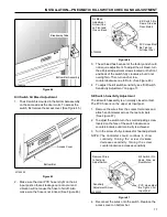
SPREADER ASSEMBLY
Door without Hood Assembly
1. Attach an L-shaped support bracket to each end of
the spreader extrusion using two 3/8-16 x 1 1/4-in.
serrated-flange hex screws and nuts. The brackets
and mounting hardware were shipped in the small
parts carton. (See Figure 14.)
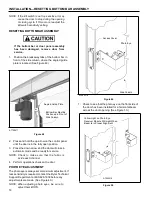
2. Attach the spreader assembly to the inside face of
each side column using two 3/8-16 x 1 1/4-in.
serrated-flange hex screws and nuts at each end of
the assembly. Face the spreader so the brush is
toward the front of the door. (See Figure 15.)
L-Bracket (Fits
Behind Inside
Face of Side
Column)
Serrated-Flange
Hex Nut (Two
on Each End)
Serrated-Flange
Hex Screw (Two
on Each End)
Inside Face of
Side Column
A7700025
Figure 15
3. Check that the side columns are plumb and square
with the floor and wall.
4. Tighten all anchor hardware securing both side
columns (or pullouts) to the wall.


