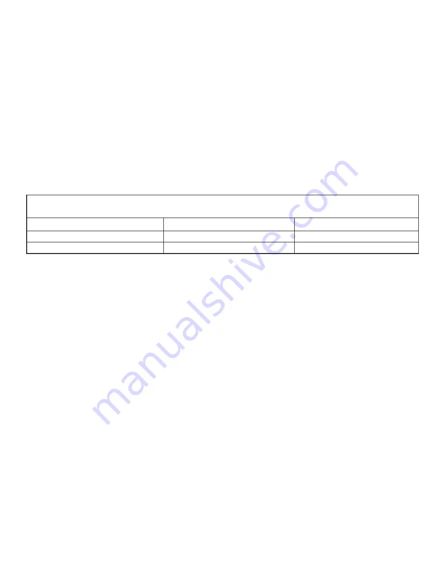
RUTHMAN Gusher Pumps 7071 Series Instruction Manual Download Page 25

TABLE 5

7071 SERIES SHAFT RUNOUT TOLERANCES


SLEEVE FIT 

COUPLING FIT


WITH SLEEVE 

.002 

.001


WITHOUT SLEEVE 

.001 

.001

25

4.  Inspect  the  shaft  (9)  and  sleeve  (16)  for 

grooves or pitting, replace if any are found. 
Ensure  the  shaft  bearing  fits  are  within  the 
tolerances in Table 4. Also, check that shaft 
runout does not exceed the values in Table 
5. 

5.  Inspect the bearing frame (13) and pedestal 

(14) for cracks. Remove all loose foreign ma-
terial  from  inside  the  frame.  Ensure  that  all 
lubrication passages are clear. 

6.  Inspect  stem  plate  (23)  for  pitting  or  wear 

greater than 1/8” deep, and make sure that 
the gasket surface is clean. 

7.  Inspect  the  bearing  housing  (6)  for  cracks 

and pitting. Check that the bore is within the 
tolerances. Replace bearing housing if bore 
exceeds these tolerances. 

8.  Inspect  the  bearings  (5  &  10)  for  contami-

nation or damage. If bearing damage is not 
from normal wear, correct the problem be-
fore using pump. Do not reuse bearings. 

Summary of Contents for Gusher Pumps 7071 Series

Page 1: ...tion manual 7071 SERIES ANSI STANDARD DIMENSION AND VORTEX PROCESS INDUSTRY PUMPS GUSHER PUMPS INC 115 INDUSTRIAL DRIVE WILLIAMSTOWN KY 41097 PHONE 859 824 3100 FAX 859 824 7428 www gusher com MAINTENANCE INSTALLATION OPERATIONS ...

Page 2: ...als used in Gusher pumps provides for optimum performance and long trouble free service As with any mechanical device proper use and periodic maintenance will enhance the performance and life of your pump This manual is provided as a guideline for proper installation operation and maintenance THIS MANUAL MUST BE READ AND UNDERSTOOD BEFORE INSTALLING AND OPERATING ANY 7071 SERIES ANSI STANDARD DI M...

Page 3: ...3 TABLE OF CONTENTS GENERAL INFORMATION 4 INSTALLATION 7 OPERATION 14 MAINTENANCE 17 DISASSEMBLY 22 REASSEMBLY 26 APPENDIX 32 ...

Page 4: ... will result if proce dures outlined in this manual are not followed NEVER operate pump below recommended minimum flow or when dry ALWAYS lock out power to the motor before performing pump maintenance NEVER operate pump without safety devic es installed NEVER operate pump with discharge valve closed NEVER operate pump with suction valve closed DO NOT change conditions of service with out approval ...

Page 5: ...nd withstands greater axial and radial thrust loads External Impeller Adjustment Like new clear ance can be maintained with simple external adjustment in just minutes to maintain original high efficiencies Rabbeted Fits Accurately machined rabbets ensure positive alignment longer seal life easy replacement of spare rotating element when maintenance is required Contained Casing Gasket Protects agai...

Page 6: ...ing to be installed within six months several precautions must be tak en 1 Preservative treatment of bearings and ma chined surfaces is required 2 Remove packing on pumps with packed stuffing box the stuffing box and shaft sleeve must be oil lubricated to also protect against moisture 3 Units equipped with mechanical seals must also be oil lubricated with an oil can through the NPT port while rota...

Page 7: ... out of stor age all of the grease or preservative must be removed from the ball bearing housing The ball bearing housing must then be thoroughly cleaned with kerosene or carbon tetrachloride and relubricated On packed pumps it will be necessary to clean the shaft sleeve and stuffing box with kerosene or carbon tetrachloride and then repack LOCATION FOUNDATION Whenever possible locate pump far eno...

Page 8: ...n bolt Fab Steel It should be noted at this time that SPECIAL CARE must be taken when leveling your pump for alignment it is of the utmost importance Once the pump is set the only means of adjust ing is by shimming 1 Place 12 wedges on the foundation one wedge on each side of every mounting bolt Place wedges so that baseplate is 3 4 above foundation to allow for adequate grouting Fig 4 2 Carefully...

Page 9: ...nd the other across the middle of both pump pads 8 Adjust the jack screws to level the pump pads in both directions 9 Install the anchor bolts until they are hand tight 10 Recheck the motor pads for level measure ments 11 Continue adjusting the jackscrews and an chor bolts until all level measurements are within the requirement of 0 002 on in ft COUPLING ALIGNMENT PROCEDURE WARNING Before starting...

Page 10: ...around the periphery of the coupling DO NOT rotate the coupling If offset exceeds 010 realign the coupling If a correction is necessary to either the angular or parallel alignment remember to recheck the other for proper alignment TABLE 1 COLD SETTING OF PARALLEL VERTICAL ALIGNMENT Pumpage Temperature Set Driver Shaft 50O F 10O C 002 in Low 150O F 65O C 001 in High 250O F 120O C 005 in High 350O F...

Page 11: ...justments that may be necessary and tight en foundation bolts securely Guidelines for piping are given in the Hydraulic Institute Standards available from the Hydrau lic Institute 30200 Detroit Road Cleveland OH 44145 1967 and must be reviewed before in stalling pump Never force piping into position by pulling it in place with the pump suction and dis charge flange bolts This will cause mis alignm...

Page 12: ...ig 7 Suction piping should never be smaller than the pump suction 3 Never throttle pump on the suction side al ways control flow by throttling on the dis charge side of the pump 12 NPSHA must always exceed NPSHR as shown on Gusher performance curves Reference Hydraulic Institute for NPSH and pipe friction values needed to evalu ate suction piping WARNING 4 When using a strainer on the suction inst...

Page 13: ...Discharge Piping 1 A gate valve and check valve should be in stalled in the discharge line The check valve should be installed between the gate valve and the pump Fig 7 this will allow for in spection of the check valve The gate valve is required for priming flow regulation and for maintenance of the pump The check valve is required to prevent pump or seal damage from reverse flow through the pump...

Page 14: ...otation 4 Make sure everyone is clear Jog motor starter pump must rotate clockwise when viewing from the driving end looking over the motor Direction arrows are cast in im peller housings Check Impeller Clearance Before starting pump the impeller clearance must be checked The pump efficiency is main tained when the proper impeller clearance is set When pumping liquids under 200O F 93O C the impell...

Page 15: ...e air vent 4 The pump will remain primed unless the foot valve leaks or if the liquid is contaminated and does not allow foot valve to close tight With an ejector 1 Mount ejector at the highest point in the im peller housing to ensure removal of all the air in the casing and suction pipe 2 Operate ejector with gate valve in discharge line closed 3 Operate until ejector discharges a full steady flo...

Page 16: ...proximately 30 drops per minute Never tighten packing enough to stop all leakage a slight leakage is required to lubricate packing and prevent scoring of shaft sleeve 4 Check pump for vibration levels bearing temperature and excessive noise If normal levels are exceeded shut down and investi gate Always vary the capacity with gate valve in the discharge line Never restrict intake flow If the speci...

Page 17: ...ricated A high quality turbine oil with rust and oxida tion inhibitors such as Mobil DTE 26 300 SSU or its equivalent should be used Fill bearing frame with oil until level is at the center of the sight glass Grease Lubricated 1 When regreasing ensure the grease contain er greasing device and the grease fittings are clean to prevent impurities from entering the bearing housing 2 Remove the 2 greas...

Page 18: ...k bearing by lifting shaft up and down do not expect packing to act as a bearing 2 Use the right cross section of packing Gusher uses Non Asbestos packing as our standard for general purpose applications Packing for special applications available consult factory 3 When using coil or spiral packing always cut the packing into separate rings Never wind a coil of packing into a stuffing box Rings can...

Page 19: ...specified Gusher can provide means of lubricating the shaft and packing through a lantern ring by supplying water oil grease or liquid handled in the pump 8 If the stuffing box has a lantern ring make sure the lantern ring as installed is slightly behind the fluid inlet as gland pressure is applied Fig 9 9 Replace packing when leakage cannot be controlled by further take up on the gland Some of th...

Page 20: ...icator to zero and loosen locking screws about one turn 7 Tighten the adjusting screws evenly back ing the impeller away from the housing until the indicator shows the required clearance 8 Tighten the locking screws and jamb nuts evenly being sure to maintain the proper clearance 9 Check shaft for free turning then reinstall coupling and guards Using a feeler gauge 1 Remove coupling guards see App...

Page 21: ...too small Foot valve is too small Foot valve or suction opening not sub merged deep enough Vibration Bent shaft Pipe strain Impeller clogged Coupling alignment off Not enough pressure Speed too low Air in water Mechanical defects Wear ring is worn Impeller damaged Impeller diameter too small Pump works for a while then loses suction Leaky suction line Water seal plugged Impeller clogged Air or gas...

Page 22: ... Induction Bearing Header Cleaning Agents DISASSEMBLY Pump and components are heavy Serious physcial injury or damage to equipment could occur from failure to properly lift and support pump Steel toed shoes must be worn at all times WARNING Operator must be aware of pumpage and safety precautions to prevent physical in jury Proper personal protective equipment should be worn WARNING Lock out motor...

Page 23: ...ing as sembly To remove impeller place shaft wrench on shaft and rotate impeller clock wise viewed from impeller end of assem bly raising wrench off work surface Quickly turn impeller opposite direction impacting wrench handle against solid block or work surface Repeat process until impeller loos ens Fig 12 If impeller cannot be removed by the meth od described above the shaft can be cut between t...

Page 24: ...ut 4 from shaft 25 Slide bearing housing 6 off of thrust bear ing 5 26 Remove bearings 5 and 10 and bearing housing 6 from the shaft 27 Remove bearing housing o ring 7 from bearing housing 28 Remove bearing frame breather 12 and pedestal 14 from bearing frame 13 After disassembly the parts must be inspected to ensure that they will function properly after reassembly Any parts that do not meet the ...

Page 25: ...3 and pedestal 14 for cracks Remove all loose foreign ma terial from inside the frame Ensure that all lubrication passages are clear 6 Inspect stem plate 23 for pitting or wear greater than 1 8 deep and make sure that the gasket surface is clean 7 Inspect the bearing housing 6 for cracks and pitting Check that the bore is within the tolerances Replace bearing housing if bore exceeds these toleranc...

Page 26: ...lug in the bearing frame 13 and hand tighten 2 Install the thrust bearing 5 on shaft 9 for bearing installation procedure see Appendix 4 3 Thread locknut 4 onto shaft and tighten until snug 4 Place the snap ring 6 over the shaft with the flat side facing the bearing 5 Install the radial bearing 10 on the shaft see Appendix 4 6 Place new o ring 7 onto bearing housing 2 and coat inside of bearing ho...

Page 27: ...n until snug On M power frame use snap ring 4 4 Coat outside of thrust bearing 5 and the inside of bearing housing 6 with oil Install bearing housing onto shaft bearing assem bly Do not force assembly together 5 Install thrust bearing retainer 2 gasket 3 and bolts Torque bolts per Table 6 and check shaft for free turning 6 Install radial bearing 10 onto shaft for bearing installation procedure see...

Page 28: ... impeller 26 onto shaft Hand tighten then rotate impeller one turn If read ing varies more than 002 in disassemble power frame and determine cause Remove impeller and shaft sleeve Fig 18 4 Check bearing frame face runout Rotate shaft as indicator rides along face of frame for one turn If reading varies more than 001 in disassemble frame and determine cause Fig 19 5 Install stem 18 to bearing frame...

Page 29: ...ct with sleeve 13 Next raise shaft wrench off work surface counterclockwise if viewed from impeller end of pump then slam it back down onto work surface or a solid block Repeat pro cess a few times to tighten impeller Fig 22 14 Loosen locking and jacking screws in bear ing frame Using a feeler gauge adjust im peller until there is a 030 clearance be tween the impeller and stem plate Tighten jackin...

Page 30: ...ith mechanical seal onto shaft 7 Then mount stem plate 23 to stem 8 Reinstall impeller following same method previously used 9 Mount seal gland 19 to stem plate Packed Pumps 1 Install packing and gland according to pro cedures in the Maintenance section of this manual All Models 1 Clean fits between rotating assembly and impeller housing 26 2 Place stem plate gasket 24 on stem 3 Loosen locking and...

Page 31: ...lined in the Maintenance section of this manual 9 Check to see that it is possible to rotate the shaft easily by hand if so continue with startup of pump in Operation section of this manual If shaft does not turn easily deter mine cause and correct ASSEMBLY TROUBLESHOOTING Problem Cause Solution Bearing internal clearance too great Replace bearings with correct type Excessive shaft end play Snap r...

Page 32: ... Radial Bearing 10 Stem Plate Gasket 24 Snap Ring 4 Locknut 4 Impeller O Ring 17 Bearing Housing O Ring 7 Oil Seal Coupling End 1 Oil Seal Bearing Frame 15 Mechanical Seal 21 Lantern Ring Half Packed Pumps Set of Packing Packed Pumps Packing Gland Packed Pumps When ordering spare parts the following information should be provided to enable the factory to give precise and accurate information on pa...

Page 33: ...33 7071S APPENDIX 2 DRAWINGS ...

Page 34: ...34 7071M ...

Page 35: ...35 7071L ...

Page 36: ...en posi tioned around the end plate secure it with a bolt nut and two washers through the round hole in the front of the guard half 4 Spread bottom of second coupling guard half and place it over the first half ensure that the annular groove is faces the motor Fig 29 5 Place second end plate over the motor shaft and position it in the annular groove of the second guard half Secure end plate using ...

Page 37: ...am pres sure against a piece of soft metal tubing as shown in Fig B The tubing must be clean inside and out and the inside diameter of the tubing should be slightly greater than the bearing bore The ends of the tubing should be square with corners chamfered to avoid flaking and should contact only the bearing inner ring The shaft must be held in line with the ram of the arbor press to avoid cockin...

Page 38: ... CL3X4 10BSE 50 41 50 41 33 27 25 CL4X6 10SE 100 82 66 54 50 CL4X6 10BSE 150 123 150 123 98 80 75 CL4X5 11SE 150 123 98 80 75 CL6X8 11SE 150 123 98 80 75 CL1 5X3 13 SE 50 41 50 41 33 27 25 CL2X3 13SE 50 41 50 41 33 27 25 CL3X4 13SE 100 82 100 82 66 54 50 CL4X6 13SE 200 164 131 107 99 CL4X6 13SHC 200 164 131 107 99 CL6X8 13SE 400 328 262 214 199 CL6X8 13SHC 400 328 262 214 199 CL8X10 13SE 500 410 3...

Page 39: ...of California 8226 Salt Lake Avenue Cudahy CA 90201 Phone 323 773 0847 Fax 323 773 0958 Email www gusherca aol com Gusher Pumps of New Castle 403 North Ninth Street New Castle IN 47362 Phone 765 529 5624 Fax 765 521 0008 Email www gusherpump insightbb com BSM Pump Corp 180 Frenchtown Road North Kingstown RI 02852 Phone 401 471 6350 Fax 401 471 6370 Web www bsmpump com Nagle Pumps 1249 Center Avenu...

Reviews: