background image

All-in-One Presentation System

VXP-82

22

CHAPTER 3  |  INSTALLATION AND OPERATION

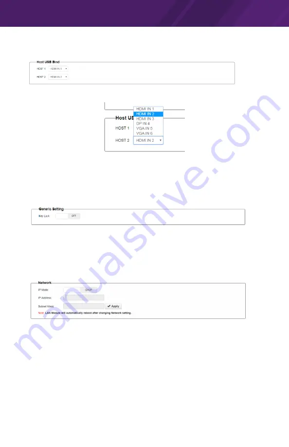
(5) Host USB Bind

This section allows USB ports to be configured to bind with inputs (Except for HDBT IN).

By default, USB HOST1 is set to bind with HDMI IN1 and USB HOST2 is set to bind with 

HDMI IN2.

SETTINGS

(1) General Setting

This section allows you to lock the buttons on switcher.

• 

ON: 

Click to enable KEY LOCK.

• 

OFF: 

Click to disable KEY LOCK.

By default, KEY LOCK is set as OFF.

(2) Network

Network is used to set between the dynamic and static IP address.

• 

DHCP: 

When enabled, the IP address of the Matrix is assigned automatically by the 

DHCP server connected.

• 

Static: 

When enabled, set up the IP address manually.

• 

Apply: 

Click to enable the network setting.

By default, the Network is set as DHCP IP address.

Note: 

• 

When “Static” is selected, please ensure your PC is in the same network segment as 

the Matrix, i.e. the IP address of your PC should be set as 192.168.xxx.xxx.

• 

Please wait for about 30 seconds for LAN module to reboot and reconnect after the 

network setting is changed.

Summary of Contents for VXP-82

Page 1: ...1 It s Under Control Installation and Operation Guide 70 210210 13 V1 1 It s Under Control VXP 82 VXP 82 All in one Presentation System...

Page 2: ...the equipment and the receiver Connect the equipment into an outlet on a circuit different from that to which the receiver is connected Consult the dealer or an experienced radio TV technician for he...

Page 3: ...Cord Grounding Plug Do not remove the grounding prong of the grounding type plug A grounding type plug has two blades and a third grounding prong The third prong is provided for your safety If the pr...

Page 4: ...ial and workmanship in this product The following are not covered by the warranty Damage resulting from 1 Accident misuse abuse or neglect 2 Failure to follow instructions contained in this Guide 3 Re...

Page 5: ...apter 1 Welcome 7 Important Notes 8 Product Contents 8 Chapter 2 Features and Description 9 Front Panel 10 Rear Panel 11 Pinout 14 Chapter 3 Installation and Operation 15 Wiring and Connections 15 Web...

Page 6: ...All in One Presentation System VXP 82 6...

Page 7: ...unit With support for multiple AV inputs and outputs built in control and HDBaseT communication the VXP 82 enables presentations in two rooms simultaneously The VXP 82 8x2 multi format matrix switch...

Page 8: ...carrier immediately Report any equipment malfunctions to RTI or an authorized RTI distributor IMPORTANT NOTES Please read these important notes about the VXP 82 The VXP 82 should be placed in an area...

Page 9: ...rs in addition to Ethernet IR and RS 232 pass through Supports Auto CEC control set through driver commands or Web UI Bi directional KVM functionality for HDMI or HDBaseT outputs Ideal for presentatio...

Page 10: ...on Press to select VGA IN5 source as input 8 VGA IN6 Selection Press to select VGA IN6 source as input 9 HDBT IN7 Selection Press to select HDBT IN7 source as input 10 HDBT IN8 Selection Press to sele...

Page 11: ...control system separate if needed G LAN Connect to an Ethernet network to enable telnet or web UI Control H RTI COM Connect to a ZM 24 Zigbee transceiver module for two way communication with RTI hand...

Page 12: ...for external devices such as IR or RF receivers Internally tied to power jack S GROUND Ground connection for devices connected to 12VDC SIGNAL IN or HIGH OUT terminals T SIGNAL IN Used to connect to a...

Page 13: ...C HDMI OUT Connect to an HDMI display D HDBT OUT Connect to VXP R HDBaseT Extender or compatible HDBaseT receiver via a Cat 5e 6 7 cable E FW PORT Service use only F SCALER Service use only G HDMI HD...

Page 14: ...N cables DB 9 Pin Signal Signal Name Description 1 DCD Carrier Detect 2 RXD Receive Data 3 TXD Transmit Data 4 DTR Data Terminal Ready 5 GND Signal Ground 6 DSR Data Set Ready 7 RTS Request To Send 8...

Page 15: ...ect USB devices to USB DEVICE ports See USB Configuration Notes below 7 One way PoE enables the switcher to power the remote HDBaseT receiver along a single Cat cable 8 Power on all attached devices N...

Page 16: ...er SET POWER STATUS HDCP LINK Model VXP R HDBaseT Extender Receiver RS232 HDBT IN HDMI OUT IR IN IR OUT S PDIF IN S PDIF OUT DC 12V TX RX ETHERNET AUDIO OUT USB HOST USB DEVICE Ethernet Switch Etherne...

Page 17: ...ay 3 Enter the default password admin and click Login Web UI Introduction The Web UI main page includes several tabs for basic and advanced settings including Video Control Audio Control Configuration...

Page 18: ...n white to green to select the audio input for the output By default De EMBED IN1 routes to AUDIO OUT1 and HDMI OUT DE EMBED IN2 routes to AUDIO OUT2 and HDBT OUT De embedded Audio of HDMI OUT De embe...

Page 19: ...io input Mute Click to mute unmute audio output By default the volume of MIC LINE audio input is 0dB CONFIGURATION 1 Input HDCP This section allows you to enable or disable HDCP capability of each inp...

Page 20: ...tting of each input port CHAPTER 3 INSTALLATION AND OPERATION Apply Click to enable the EDID setting To set up the EDID setting for HDMI IN1 Go to the HDMI IN1 and select the settings from its drop do...

Page 21: ...utomatically when there s no signal at the display for 3 minutes By default CEC Auto Control is set to ON 4 Output Resolution Configure EDID setting of each input port Set the scaler for HDMI OUT and...

Page 22: ...default KEY LOCK is set as OFF 2 Network Network is used to set between the dynamic and static IP address DHCP When enabled the IP address of the Matrix is assigned automatically by the DHCP server co...

Page 23: ...pgrade This section allows you to upgrade the Web UI To update the Web UI 1 Click Browse for the update bin file 2 Then click Upgrade to proceed 5 System This section allows you to reboot or reset the...

Page 24: ...ctory defaults Click Factory Reset and then click OK in the pop up window Then wait 30 seconds to refresh and re login the Web UI CHAPTER 3 INSTALLATION AND OPERATION 6 Firmware Version This section a...

Page 25: ...maximum per port adjustable 200mA maximum high IR output port IR Frequency Transmission Range 15kHz 460kHz Trigger Outputs Three 12 VDC 100mA max each Relays Three 30VDC 5 Amps Sense Inputs Three 3 24...

Page 26: ...eT PoH RJ45 Resolution Range 800 x 600 60Hz to 4K x 2K 60Hz HDBaseT Transmission Distance 1080p 60Hz 100m 4K x 2K 60Hz 90m Switching Seamless EDID Management Built in EDID data and manual EDID managem...

Page 27: ...s or have a question about your RTI product please contact RTI Technical Support for assistance see the Contacting RTI section of this guide for contact details RTI provides technical support by telep...

Page 28: ...on System VXP 82 28 Remote Technologies Incorporated 5775 12th Avenue East Suite 180 Shakopee MN 55379 Tel 952 253 3100 Fax 952 253 3131 www rticorp com 2019 Remote Technologies Inc All rights reserve...

Reviews: