


ROYAL ENFIELD WORKSHOP MANUAL
distance collars, 41373 and 41372, chain adjuster
cams, the loose section of the spindle and the
spindle nut, 28832. The wheel is then ready for
reassembly into the machine.
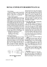
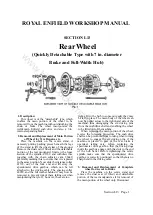
14. Wheel Rim
The wheel rim is type WM2-19 in. plunged and
pierced with forty holes for spoke nipples. The
spoke holes are symmetrical, i.e., the rim can be
assembled to the hub either way round. The rim
diameter after building is 19.062 in., the tolerances
on the circumference of the rim shoulders where
the tyre fits being 59.930/59.870 in. The standard
steel measuring tape for checking rims is 5/16 in.
wide, .011 in. thick, and its length is
59.964/59.904in.
The "350 Bullet" details are as given below:
The wheel rim is type WM2-17 in. plunged and
pierced with forty holes for spoke nipples. The
spoke holes are symmetrical, i.e. the rim can be
assembled to the hub either way round. The rim
diameter after building is 17.062 in., the tolerances
on the circumference of the rim shoulders where
the tyre fits being 53.642/53.582 in. The standard
steel measuring tape for checking rims is 5/16 in.
wide, .011 in. thick, and its length is 53.676/53.616
in.
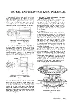
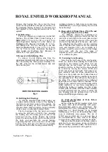
The spokes are of the single-butted type, 8-10
gauge, with 90° countersunk heads, thread
diameter .144 in., 40 threads per inch, thread form
British Standard Cycle. The inner spokes are 5.5/8
in. long with an angle of bend 100°, and the outer
spokes 5.3/4 in. long with an angle of bend 80°.
15. Spokes.
The spokes are of the single butted type, 8-10
gauge, with 90° countersunk heads, thread
diameter, .144 in., 40 threads per inch, thread form
British Standard Cycle. The inner spokes are 6.5/8
in. long with an angle of bend 100°, and the outer
spokes 6.3/4 in. long with an angle of bend 80°.
"Works Replica" up to 1960 and "500 Bullet" up
to 1961: inner and outer spokes 6.5/8 in."350
Bullet" up to 1958: 6.5/8 in. and 6.3/4 in."350
Bullet" 1959 onwards, "350 Clipper" 1960
onwards: 5.3/4 in. and 5.5/8 in.
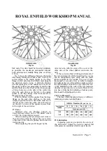
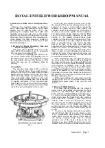
16. Wheel Building and Truing
The spokes are laced one over two and the
wheel rim must be built central in relation to the
outer faces of the distance collars 41373 and
41372. The rim should be trued as accurately as
possible, the maximum permissible run-out both
sideways and radially being plus or minus 1/32 in.
17. Tyre
Sizes are as follows:
"350 Clipper" 1960 onwards: 3.25-17 in.
"350 Bullet" 1959 onwards: 3.25-17 in.
"500 Bullet" up to 1959: 3.50-19 in.
"500 Bullet" 1960 onwards: 3.25-19 in.
When removing the tyre always start close to
the valve and see that the edge of the cover at the
other side of the wheel is pushed down into the
well in the rim.
When replacing the tyre fit the part by the valve
last, also with the edge of the cover at the other
side of the wheel pushed down into the well.
If the correct method of fitting and removal of
the tyre is adopted it will be found that the covers
can be manipulated quite easily with the small
levers supplied in the toolkit. The use of long levers
and/or excessive force is liable to damage the walls
of the tyre. After inflation make sure that the tyre is
fitting evenly all the way round the rim. A line
moulded on the wall of the tyre indicates whether
or not the tyre is correctly fitted. If the tyre has a
white mark indicating a balance point, this should
be fitted near the valve.
18. Tyre Pressures
The recommended pressures for the rear tyre
are 16 lb. per square inch for wheel loads not
exceeding 280lb., 18 lb. per square inch for loads
up to 320lb., 20 lb. per square inch for loads up to
350lb., 24 lb. per square inch for loads up to 400
lb., 28 lb. per square inch up to 450lb., and 32 lb.
per square inch up to 500 lb.
19. Lubrication
Grease the bearings by packing them with
grease after dismantling the hub as described
above.
Note that the brake cam is drilled for a grease
passage but the end of this is stopped up with a
countersunk screw instead of being fitted with a
grease nipple. This is done to prevent excessive
greasing by over-enthusiastic owners. If the cam is
smeared with grease on assembly it should require
no further attention but in case of necessity it is
possible to remove the screw, fit a grease nipple in
its place and grease the cam by this means.
Section L13 Page 5
www.hitchcocksmotorcycles.com
Summary of Contents for 350 BULLET 1956
Page 7: ...ROYAL ENFIELD WORKSHOP MANUAL w w w h i t c h c o c k s m o t o r c y c l e s c o m ...
Page 57: ...ROYAL ENFIELD WORKSHOP MANUAL w w w h i t c h c o c k s m o t o r c y c l e s c o m ...
Page 69: ...ROYAL ENFIELD WORKSHOP MANUAL w w w h i t c h c o c k s m o t o r c y c l e s c o m ...
Page 77: ...ROYAL ENFIELD WORKSHOP MANUAL w w w h i t c h c o c k s m o t o r c y c l e s c o m ...


