

ROYAL ENFIELD WORKSHOP MANUAL
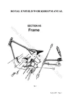
1. Description of Frame
The frame is built throughout of cold drawn
weldless steel tubing with brazed or welded
joints, liners being fitted where necessary for
extra strength. All the main frame members are
made of chromemolybdenum alloy steel tubing
which retains its strength and resistance to
fatigue after brazing or welding.
The swinging arm unit which forms the
chain stays is fitted with large diameter
phosphor bronze bushes and pivots on a stout
steel tube which is secured to the main frame by
a long bolt passing through the pivot lugs.
Hardened steel thrust washers are provided to
deal with side thrust. The torsional rigidity of
the swinging arm unit helps to maintain the rear
wheel upright in the frame and thus relieves the
wheel spindle of bending stresses to which it is
subject with other types of rear suspension.
2. Steering Head Races
The steering head races, 34085, are the same
at the top and bottom of the head lug and are
the same for all models. They are easily
removed by knocking them out with a hammer
and drift and new races can be fitted either
under a press or by means of a hammer and a
wooden drift.
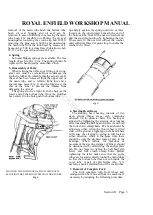
3. Removal of Rear Suspension unit
'
On the "Constellation" and "Super Meteor"
from 1961 onwards, the valances on either side
of the frame must be removed to gain access to
thetop pivot pin. See Section C, paragraph 8.)
The procedure for all models is then as
follows. Remove the top pivot pin nut, drive
out the pivot pin, then hinge the suspension
unit back on the lower pivot pin. After
removing the lower nut, the unit may be pushed
off the pivot pin welded to the fork end.
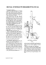
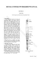
4. Servicing Rear Suspension Units
The proprietary units fitted are sealed and
servicing of the internal mechanism can be
carried out only by the manufacturers.
The rubber bushes in the top and bottom
eyes can easily be renewed and the spring can be
removed by pushing down on the top spring
cover so as to release the split collar above it.
After removal of the split collar the top cover
and spring can be lifted off. When reassembling,
the spring should be greased to prevent rust and
squeaking if it should come into contact with
either of the covers.
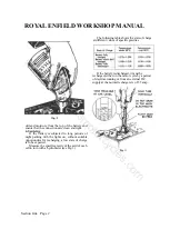
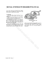
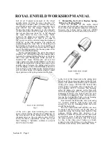
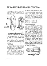
The standard solo springs have a rate of 100
105 lb. per inch and it is not difficult to
compress these by hand. Heavier springs having a
rate of 130 lb. per inch are available which may
require the use of a spring compressor, as shown
in Fig. 2.
5. Removal of Swinging Arm Chain Stays
First remove one of the pivot pin nuts and pull
the pivot pin out from the other end. To release
the pivot bearing it is necessary to spread the rear
portion of the frame, using the frame expander
E.5431, which will spread the frame sufficiently to
enable the spigots on the thrust washers to clear
the recesses in the pivot lugs forming part of the
frame.
Section H5 Page 2
www.hitchcocksmotorcycles.com
Summary of Contents for 350 BULLET 1956
Page 7: ...ROYAL ENFIELD WORKSHOP MANUAL w w w h i t c h c o c k s m o t o r c y c l e s c o m ...
Page 57: ...ROYAL ENFIELD WORKSHOP MANUAL w w w h i t c h c o c k s m o t o r c y c l e s c o m ...
Page 69: ...ROYAL ENFIELD WORKSHOP MANUAL w w w h i t c h c o c k s m o t o r c y c l e s c o m ...
Page 77: ...ROYAL ENFIELD WORKSHOP MANUAL w w w h i t c h c o c k s m o t o r c y c l e s c o m ...


