


ROYAL ENFIELD WORKSHOP MANUAL
SECTION L13
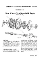
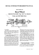
Rear Wheel
(Quickly Detachable Type with 7 in. diameter
Brake and Full-Width Hub)
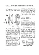
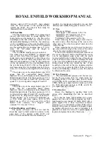
1. Description
This wheel is of the "detachable" type, which
enables the main portion of the wheel to be
removed from the machine without disturbing the
chain or brake. The wheel incorporates the
well-known Enfield cush drive and also a 7-in.
internal expanding brake.
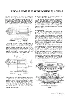
2. Removal and Replacement of Main Portion
of Wheel for Tyre Repairs, etc.
Place the machine on the centre stand, if
necessary putting packing pieces beneath the legs
of the stand to lift the wheel clear of the ground.
Remove the dual seat (if fitted) and the detachable
portion of the rear mudguard. Unscrew the loose
section of the spindle, 41369, and withdraw this,
together with the chain adjuster cam, 36649,
preferably marking this to ensure that it is replaced
in the same position. Now slide the distance collar,
41372, out of the fork end and lift away the
speedometer drive gearbox, which can be left
attached to the driving cable. The spacing collar,
40989, and the felt washer behind it may now be
removed to prevent risk of them falling out when
manipulating the tyre. If, however, these are too
tight a fit in the hub to come out easily they may
be left in place. The main body of the wheel can
now be pulled across to the right-hand side of the
machine, thus disengaging the six driving pins
from the cush drive shell and enabling the wheel
to be lifted out of the machine.
When replacing the main portion of the wheel,
reverse the foregoing procedure. The cush drive
shell can be prevented from rotating when turning
the wheel to engage the six driving pins, if the
machine is placed in gear or the rear brake is
operated, taking care, when replacing the
speedometer drive gearbox, that the driving dogs
inside the gearbox engage with the slots in the end
of the hub barrel. Before tightening the centre
spindle make sure that the speedometer drive
gearbox is correctly positioned so that there is no
sharp bend in the driving cable.
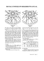
3. Removal and Replacement of Complete
wheel for Access to Brake
Place the machine on the centre stand and
remove the dual seat (if fitted) and detachable
portion of the rear mudguard as if for removal of
the main portion of the wheel only. Disconnect
Section L13 Page 2
the rear driving chain at the spring link and remove
the chain from the rear wheel sprocket leaving it in
position on the gearbox countershaft sprocket.
Unscrew the rear brake rod adjusting nut
completely and depress the brake pedal so as to
disengage the rod from the trunnion in the brake
operating lever. Unscrew the brake cover plate
anchor nut, 7598, and remove this together with the
washer behind it. Unscrew the loose section of the
spindle, 41369, two or three turns and the spindle
nut, 28832, by a similar amount. Mark the chain
adjuster cams to ensure replacing in the same
position.* Disconnect the speedometer driving
cable and slide the wheel out
Note that the wheel is not necessarily
correctly lined up when the same notch
position is used on both adjuster cams. Once
the position of the cams which gives correct
alignment has been found this alignment will,
however, be maintained if both cams are
moved the same number of notches.
of the fork ends, tilting it so as to disengage the
end of the brake shoe pivot pin from the slot in
the fork end.
When replacing the wheel make sure that the
dogs on the gear in the speedometer drive gearbox
are engaged with the slots in the end of the hub
barrel. Make sure also that the speedometer drive
gearbox is correctly positioned so that there is no
sudden bend in the driving cable. When replacing
the connecting link in the driving chain make sure
that the closed end of the spring link points in the
direction of travel of the chair. Replace the chain
adjuster cams in their original positions or, if
necessary, turn each of them the same number of
notches to tension the chain and maintain correct
wheel alignment. Do not forget to refit the brake
rod and adjust the brake so that the wheel turns
freely when the brake is off, while at the same
time only a light pressure on the brake pedal is
necessary to put the brake on.
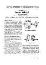
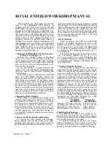
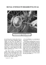
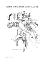
REMOVAL OF WHEEL (OFFSIDE VIEW)
Fig. 2
www.hitchcocksmotorcycles.com
Summary of Contents for 350 BULLET 1956
Page 7: ...ROYAL ENFIELD WORKSHOP MANUAL w w w h i t c h c o c k s m o t o r c y c l e s c o m ...
Page 57: ...ROYAL ENFIELD WORKSHOP MANUAL w w w h i t c h c o c k s m o t o r c y c l e s c o m ...
Page 69: ...ROYAL ENFIELD WORKSHOP MANUAL w w w h i t c h c o c k s m o t o r c y c l e s c o m ...
Page 77: ...ROYAL ENFIELD WORKSHOP MANUAL w w w h i t c h c o c k s m o t o r c y c l e s c o m ...


