

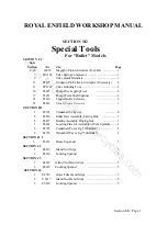
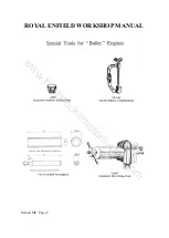
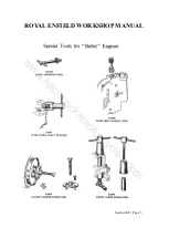
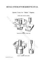
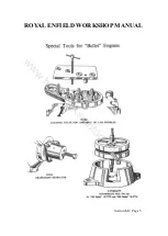
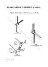
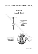


ROYAL ENFIELD WORKSHOP MANUAL
Section L13 Page 3
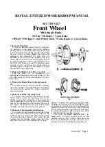
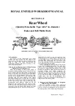
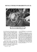
4. Removal of Brake Shoes for Replacement,
etc.
Remove the complete wheel as described
above, then remove the spindle nut, 28832, chain
adjuster and the distance collar, 41373, thus
permitting the complete brake cover plate with
operating cam, pivot pin, shoes and return
springs to be lifted off the hub spindle. The brake
shoes can then be removed after detaching the
return springs. The brake linings are bonded to
the shoes and if requiring to be renewed, should
be sent for servicing.
5. Removal of Brake Operating Cam and
Brake Shoe Pivot Pin
The pivot pin is threaded into the torque
plate, 41109, from which it can be unscrewed
after removing the locknut, 41375.
To remove the operating cam unscrew the
nut, 10314, which secures the operating lever to
the splines on the cam. A sharp tap on the end of
the cam spindle will now free the lever, after
which the cam can be withdrawn from its
housing.
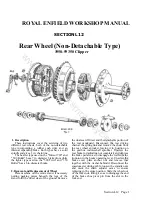
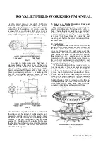
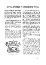
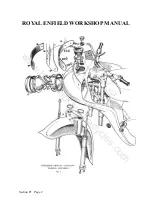
6. Cush Drive
The sprocket/brake drum, 41233, is free to
rotate on the hub barrel. Three radial vanes are
formed on the back of the brake drum and three
similar vanes are formed on the cush drive shell,
40967. Six rubber blocks are fitted between the
vanes on the brake drum and those on the cush
drive shell, thus permitting only a small amount
of angular movement of the sprocket/brake
drum relative to the hub barrel and transmitting
both driving and braking torques and smoothing
out harshness and irregularity in the former.
If the cush drive rubbers become worn so that
the amount of free movement measured at the tyre
exceeds 1/2 in. to 1 in the rubbers. should be
replaced. To obtain access to them remove the
complete wheel as described above ; then unscrew
the loose section of the spindle, 41369, completely.
The main portion of the wheel can then be lifted
away from the assembly consisting of the fixed
portion of the spindle, sprocket/brake drum
complete with brake and the cush drive shell. Now
remove the brake cover plate complete with brake
shoes as described above, and unscrew the three
nuts at the back of the cush drive shell after
bending back the locking washers. The three studs,
41002, are brazed to the lockring, 10097, and
should be driven out of the cush drive shell, each a
little at a time to avoid distorting the lockring or
bending the studs. The sprocket/brake drum can
now be separated from the cush drive shell, and the
six cush drive rubbers lifted out.
When reassembling the cush drive the entry of
the vanes between the rubbers will be facilitated if
the latter are fitted into the driving shell first and
then tilted. The rubbers should be liberally smeared
with soapsuds to facilitate entry of the vanes.
Grease the inner face of the lockring, 10097, before
assembling and tighten the three nuts down solid as
there is a shoulder on the stud which prevents
tightening of the nuts from locking the operation of
the cush drive. Do not forget to bend up the tabs of
the three locking washers.
When reassembling the cush drive, coat the
inside of the bore of the sprocket/brake drum
liberally with grease where it fits over the hub
barrel.
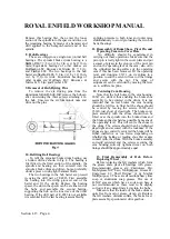
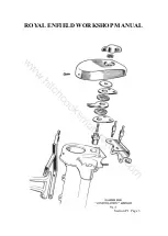
7. Removal of Ball Bearings
To remove the ball bearings take the complete
wheel out of the machine and separate the main
portion of the wheel from the sprocket/brake
drum, cush drive shell assembly, as described above.
To remove the bearing from the sprocket/ brake
drum, first remove the brake cover plate complete
with brake shoe assembly ; then remove the
distance collar, 41105, and unscrew the bearing
retaining ring, 41108, with peg spanner. Now screw
the loose section of the spindle into the fixed
section and drive out the bearing by hitting the
hexagon-headed end of the loose section of the
spindle.
To remove the bearings from the loose half of
the hub barrel, first lift away the distance collar,
41372, speedometer drive gearbox, the spacing
collar, 40989, and the felt washer, 41006. Remove
the bearing retaining circlip from the driving
sprocket end of the barrel. Between the two
bearings is a spacer, 40995, slotted at one end to
enable a drift to be used on the bearing at that end.
www.hitchcocksmotorcycles.com
Summary of Contents for 350 BULLET 1956
Page 7: ...ROYAL ENFIELD WORKSHOP MANUAL w w w h i t c h c o c k s m o t o r c y c l e s c o m ...
Page 57: ...ROYAL ENFIELD WORKSHOP MANUAL w w w h i t c h c o c k s m o t o r c y c l e s c o m ...
Page 69: ...ROYAL ENFIELD WORKSHOP MANUAL w w w h i t c h c o c k s m o t o r c y c l e s c o m ...
Page 77: ...ROYAL ENFIELD WORKSHOP MANUAL w w w h i t c h c o c k s m o t o r c y c l e s c o m ...


