


ROYAL ENFIELD WORKSHOP MANUAL
Section G2k Page 1
SECTION G2K
Lucas A.C. Lighting-Ignition System
Used on 350 Bullet and 500 Bullet, 350 Clipper and Trials
Work Replica 1961 onwards
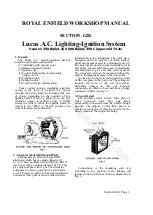
1. General
The Lucas A.C. Lighting-Ignition System
comprises seven main components
(1) Alternator with magnet rotor.
(2) Bridge-connected rectifier.
(3) Ignition coil.
(4) Contact breaker unit, and automatic
timing control.
(5) Lighting switch.
(6) Ignition switch.
(7) 6-volt battery (see Section G4a).
Under normal running conditions, electrical
energy in the form of rectified A.C. passes
through the battery from the alternator, the rate
of charge depending on the position of the
lighting switch. When no lights are in use, the
alternator output is sufficient only to trickle
charge the battery. When the lighting switch is
turned to the "Pilot" or "Head" positions the
current increases proportionately.
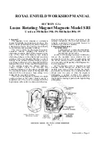
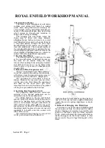
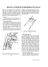
2. Alternator Models RM14 and RM15
Early models are fitted with type RM14
alternator, which has an outside diameter of'
5.7/8 in. Later models are fitted with type RM I 5
(see Fig. 1) with an outside diameter of 5 in. They
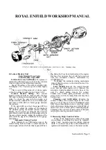
give a high output at low r.p.m. The alternator
comprises two main components, a stator and a
rotor. The stator is built up from iron laminations
and carries three pairs of series-connected coils
insulated from the laminations. The rotor has a
hexagonal steel core, each face of which carries a
permanent magnet keyed to a laminated pole tip.
The pole tips are riveted circumferentially to brass
side plates, the assembly being cast in aluminium
and machined to give a smooth external finish.
The stator and rotor can be separated without the
need to fit magnetic keepers to the rotor poles.
As the rotor turns, rapid and repeated reversals
of flux take place in the coil cores. These lines cut
through the turns of the coil and induce
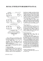
alternating voltages in that coil. External
connections are taken to these coils from a bridge
connected rectifier (see Fig. 2).
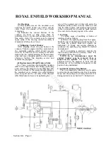
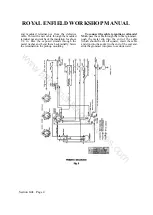
3. Circuit Detail
The alternator stator carries three pairs of
series connected coils. One pair being
permanently connected across the rectifier bridge
network. The purpose of this latter pair is to
provide some degree of charging current for the
battery whenever the engine is running.
Connections to the remaining coils vary
according to the position of the lighting and
ignition switch controls, as shown schematically in
Fig. 3.
www.hitchcocksmotorcycles.com
Summary of Contents for 350 BULLET 1956
Page 7: ...ROYAL ENFIELD WORKSHOP MANUAL w w w h i t c h c o c k s m o t o r c y c l e s c o m ...
Page 57: ...ROYAL ENFIELD WORKSHOP MANUAL w w w h i t c h c o c k s m o t o r c y c l e s c o m ...
Page 69: ...ROYAL ENFIELD WORKSHOP MANUAL w w w h i t c h c o c k s m o t o r c y c l e s c o m ...
Page 77: ...ROYAL ENFIELD WORKSHOP MANUAL w w w h i t c h c o c k s m o t o r c y c l e s c o m ...


