background image

Section 2 Installation

SG10A  Manual

www.rottlermfg.com

2-13

Summary of Contents for SG10A

Page 1: ...8029 S 200th St Kent WA 98032 USA www rottlermfg com Ph 253 872 7050 Fax 253 395 0230 OPERATION AND MAINTENANCE MANUAL 17 03 2017...

Page 2: ......

Page 3: ...model and serial number 6 Part number and description of what you want to order 7 Preferred method of shipment 8 You may also contact us via e mail with the above information Send e mail requests to p...

Page 4: ......

Page 5: ...The rest of the manual contains information and part number reference on fixtures cutting tools and machine maintenance The operator should read and become familiar with these areas as well Disclaime...

Page 6: ...officers employees or agents shall not be liable in any manner whatsoever to any person for any loss damage injury liability cost or expense of any nature including without limitation incidental spec...

Page 7: ...opy of the invoice s covering the original shipment This invoice copy must be included in the box with the parts Shipment must contain ONLY those items on the RGR as approved for return Merchandise mu...

Page 8: ...Section 1 Introduction SG10A Manual www rottlermfg com 1 4...

Page 9: ...RT 2 2 Installation Procedure 2 6 Unpacking and Lifting 2 6 Removing Shipping Brackets 2 7 Preparation for Placement 2 8 Machine Installation 2 8 Positioning the Machine 2 9 Power and Air Connections...

Page 10: ...Rottler machine please be sure to sign the installation report after the installation technician has installed the machine and verified the machine is operating correctly and given the operators oper...

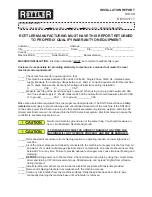
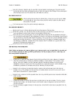
Page 11: ...verload protection The SG10A should have a fully isolated power supply to prevent damage and uncontrolled movement of the machine If the SG10A is on the same power lines that are running to other elec...

Page 12: ...mented If calibration is required refer to the manual for Calibrating the Digital Level ______Start the spindle and verify operation INSTRUCTING THE OPERATOR Note Rotter employees and representatives...

Page 13: ...al level has been calibrated rotate 180 to verify alignment ______The following is a checklist to go through every time the machine is started to begin machining a seat Work piece secure RPM set Tool...

Page 14: ...____________________________________________ ____________________________________________________________________________________ ______________________________________________________________________...

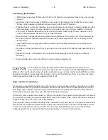
Page 15: ...angement and location for your SG10A machine is extremely important A slow travel 6 to 10 feet min power hoist operated from either a bridge crane or a jib crane arrangement works very well Unpacking...

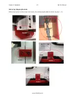
Page 16: ...Section 2 Installation SG10A Manual www rottlermfg com 2 7 Removing Shipping Brackets Before leveling the machine loosen and remove the all shipping brackets and bolts Figures 1 5...

Page 17: ...rks slightly upward so Machine will lean toward fork lift and lift Machine While Machine is on fork lift install six 6 Leveling Screws and Jam Nuts in holes provided in bottom of Machine Base Two 2 Sc...

Page 18: ...h to remove protective shipping oil Do not attempt to move the Work Head unless Air Supply is connected and air valve is turned on and power has been turn on make sure the EMERGENCY STOP Button is off...

Page 19: ...ck that Level is properly adjusted If Level does not read same in both directions recalibrate level Use the level on the upper float surface level the machine as precisely as possible front to back an...

Page 20: ...ating properly it could be from too much or too little air from the regulator Starting with all regulators set at 1 bar with workhead float button activated slowly turn all up 5 bar at a time until wo...

Page 21: ...r Connect single phase wiring to the main rear enclosure located on the right rear of machine base The connection point for power is located inside the enclosure Electrically connect in accordance wit...

Page 22: ...Section 2 Installation SG10A Manual www rottlermfg com 2 13...

Page 23: ...SAFETY Contents Safety Information 3 1 Safety Instructions for Machine Use 3 1 Electrical Power 3 3 Machine Operator 3 5 Emergency Procedure 3 6 Computer and Controller System Safety 3 6 Electrical Sa...

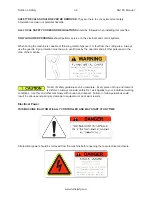
Page 24: ...lt in minor or moderate injury CAUTION used without the safety alert symbol indicates a potentially hazardous situation which if not avoided may result in property damage Safety Instructions for Machi...

Page 25: ...rther use of the machine a guard or other part that is damaged should be checked to determine that it will operate properly and perform its intended function Check for alignment of moving parts breaka...

Page 26: ...ys use the guards Eye protection must be worn at all times by the operator and all other personnel in the area of the machine No list of safety guidelines can be complete Every piece of shop environme...

Page 27: ...tible to extraneous electrical impulses internally for externally produced The machine may make moves out of the operator control at any time The operator should work in and around the machine with ca...

Page 28: ...y operation involving hands in the cutter head area such as inspection or alignment of the cutter head or tools changing Centering Fingers tool insertion and removal cutter head changes and size check...

Page 29: ...Rottler Software when not directed by Rottler personnel will result in a non operational machine The machine should be hooked up to the Internet anytime it is on The software on the machine will autom...

Page 30: ...ent sensors in all motor control panels Electrical breakers to prevent voltage surges and spikes from reaching electrical system Electrical lockout on main electrical enclosure E Stop that shuts down...

Page 31: ...2 Homing 4 3 Program select Buttons 4 5 Rapid Up Rapid Down 4 5 Feed Up Feed Down 4 5 Spindle Handwheel 4 5 Feed rate override 4 5 Spindle override 4 5 E STOP 4 5 LAMP 4 6 Center pilot 4 6 WORKHEAD F...

Page 32: ...ertical Zero 4 9 Start Cutting Height 4 9 Finish Cutting Depth 4 9 Options Screen 4 10 Dwell Options 4 10 Retract Out Options 4 10 Peck Options 4 10 Head Property Screen 4 11 General Information 4 11...

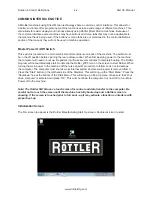
Page 33: ...ng a USB wireless Wi Fi adapter Updating the Rottler software should ONLY be done when directed to do so by a Rottler service technician Updating Rottler Software when not directed by Rottler personne...

Page 34: ...patient it will take several minutes to complete booting The Rottler program will not automatically start Double tap the Rottler_WPF icon on the screen to start Rottler When turning the main power to...

Page 35: ...d click OK The next screen to appear is the program select screen Homing 1st thing you want to do when this screen appears is to HOME the machine Buy pressing this button the computer will sync itself...

Page 36: ...keyboard or click on the on screen keyboard in the taskbar Then click OK After this click on Std Setup a box will pop up saying DELETE EVERYTHING WARNING This will delete all existing block data in XX...

Page 37: ...ding the spindle handwheel button until the screen pops up to change the speed Feed rate override You can lower and raise the FEED RATE when in the AutoCycle mode buy pressing this and turning handwhe...

Page 38: ...ditional amount of material removed after auto cycle If a seat does not clean up you can use these buttons to remove more material without changing finish cutting depth Must be below lower cutter head...

Page 39: ...s on the highest seat Float workhead and manually lower spindle with handwheel press the 001 handwheel button and use handwheel pictured on right into cutting position so cutting insert is close to se...

Page 40: ...th the machine To set this tap on the figure next to the MOVE button A keyboard will pop up enter in your height 030 and press ENTER Last is to set the FINISH CUTTING DEPTH same thing here tap the fig...

Page 41: ...or top of guide Your choice HEAD CLEARANCE HEIGHT and RAPID TO VALVE GUIDE HEIGHT is same as previously described Start Cutting Height Is set when reamer pilot is into guide enough to center but not y...

Page 42: ...o clean seat after it has been cut If you enter to many revolutions cutter will drag and possibly cause chatter Finish RPMs is the one you will need to change the most Start with 100 RPM above cutting...

Page 43: ...ge to ADD new head programs Using the keyboard type the desired name for your head click OK This will add the head to the list on the left Options To Edit a Cylinder Head Model name select a Cylinder...

Page 44: ...dit a mode select name click here and use keyboard to change Example change Seat Cut to Seat Cut INTAKE or just INTAKE press OK when done Delete To delete an operation simply highlight and press delet...

Page 45: ...t and Setup 5 5 Front to Rear Cylinder Head Alignment 5 5 Canted Valve Cylinder Heads Automotive Application 5 6 Three Angle Seat Cutting 5 7 Checking Working Range of UNI PILOT 5 8 Checking Procedure...

Page 46: ...Six and One Instructions 5 14 Adjusting the Square Carbide Inserts 5 17 Cutting Small Diameter Valve Seats 5 18 Backing Up and Restoring Block Profiles 5 19 Tooling for Counterboring Small Diameter V...

Page 47: ...usting knob Adjust the fixture to bring the carbide bit flat against the grinding wheel Make sure the carbide tip face is perfectly parallel to the wheel face by pushing it with the thumb Once a good...

Page 48: ...ach cylinder head put on the supports In most cases we will install the cylinder head deck side down with the exhaust side of the head against the adjustable stops This is particularly true of wedge s...

Page 49: ...Install the C Clamp you must use the two bolts included with the fixture and make sure is good and tight The cylinder head gasket surface must be against the machined surface of the U Clamp Fixture Sl...

Page 50: ...rame is mounted between the trunnions and clamped using the clamping plates See Pictures The cylinder head is then held to the frame with the swivel clamp assemblies through the appropriate head bolt...

Page 51: ...eveling pin is square to the machines spindle as long as you achieve the same readings front to rear and side to side then the spindle will be in perfect alignment Front to Rear Cylinder Head Alignmen...

Page 52: ...e the level on the leveling post Loosen both of the tilt lock levers on each side of the quill housing Use the tilt adjusting hand wheel to adjust the reading to be the same as that found on the pilot...

Page 53: ...lean up surface Too much cutting will sink the valve too far in the head Many operators prefer to use the spindle fine feed when machining seats as extreme control of spindle down feed can be accompli...

Page 54: ...LOT in the cylinder head valve guide 2 Place checking gauge along pilot section that is exposed above cylinder head surface 3 If pilot top is within Min Max range of the gauge then you may proceed wit...

Page 55: ...gauge and move upward approximately 1 8 The dial pointer should move as this is done Center the pointer of the indicator pointing upward and lock the gauge to the pilot using the brass locking screw T...

Page 56: ...lower spindle to start cutting height dwell to center and clamp workhead turn urn on spindle cut to finish cutting depth and then retract to preset retract height floating if checked 11 At this point...

Page 57: ...he two ears of the spindle adapter and insert into the spindle ISO 30 taper The locking nut automatically will be on the lock position to remove turn the self locking nut to the left position hold the...

Page 58: ...6 96mm 2740 In order for the pilot to fit most of the valve guides the first choice could be UCP0699 to give 01mm 0 0004 clearance If the valve guide is used and has some wear then the second choice...

Page 59: ...stance FCM20EL380 Modular Carbide Centralizing Pilot for Valve Guides Over 0 875 22 23mm Requires a set of Interchangeable Sleeves FCMSLXXX FCMSUXXX 20mmShank Pilot FCMSUXXX Modular Pilot Upper Tapere...

Page 60: ...Section 5 Operating Instructions SG10A Manual www rottlermfg com 5 14 Rottler Six and One Instructions...

Page 61: ...Section 5 Operating Instructions SG10A Manual www rottlermfg com 5 15...

Page 62: ...Section 5 Operating Instructions SG10A Manual www rottlermfg com 5 16...

Page 63: ...are tip holder offset IMPORTANT When 90 degreed bits RCA512 or the Triangle bits are fitted check that their reference faces are perfectly clean The accuracy of the seat angles depends on this While r...

Page 64: ...ew as shown in photo below push pilot all the way into the UPT5200 and tighten set screw to hold pilot inside the UPT5200 Install the Tip Holder TH1999 adjust diameter release set screw and remove pil...

Page 65: ...ction will explain how to back up and restore the operator created block profiles for DM controlled machines for archival purposes or to transfer to a different machine First step is to open your file...

Page 66: ...SG10A Manual www rottlermfg com 5 20 The following pop up box will appear on your screen Click on the Open folder to view files option and the following screen will appear This is the contents of the...

Page 67: ...Section 5 Operating Instructions SG10A Manual www rottlermfg com 5 21 Next resize and arrange both file browsers so that they are side by side...

Page 68: ...with the current profiles being shown in the RottlerWPF folder All that needs to be done to back up the current profile is to simply drag it from the RottlerWPF folder to the flash drive folder A copy...

Page 69: ...G10A Manual www rottlermfg com 5 23 To restore or add block profiles go through the first 5 steps explained previously Highlight the block profiles file in the flash drive and drag it into the Rottler...

Page 70: ...ction 5 Operating Instructions SG10A Manual www rottlermfg com 5 24 You will get a pop up window about there being a file of the same name in the destination folder Click on the Copy and Replace optio...

Page 71: ...on 5 Operating Instructions SG10A Manual www rottlermfg com 5 25 The archived block profiles will now be installed Close both browser windows and remove the flash drive The restore process is now comp...

Page 72: ...26 80 mm 35 55 mm BH600R1 Mini Spherical Toolholder TH1999 Tip Holder RCA513 Seat Cutting Insert Bore diameter 800 1 200 20 80 mm 30 48 mm 375 Pilot Combos BH375R1 Spherical Toolholder TH2000 00 Tip H...

Page 73: ...nce Lubrication Chart 6 1 Preventative Maintenance Quick Reference Chart 6 1 Air Adjustments 6 2 Float 6 2 Float surfaces 6 2 Calibrating the Digital Level 6 3 Spindle 6 3 Adjusting And Aligning The O...

Page 74: ...se rollover clamp fixture bearings 200 Hours Clean and grease NLGI 2 White Lithium Grease Grease clamp fixture Pins and Acme screw 200 Hours Clean and grease NLGI 2 White Lithium Grease Preventative M...

Page 75: ...agging in the forward position workhead pulled closest to operator raise the 2 front regulators 1 mark until it floats without dragging Same for rear You may have to go back and forth a few times to g...

Page 76: ...head left or right until level reads 0 00 Now rotate level 180 degrees The reading should be 0 00 if not then it will be necessary to calibrate the inclinometer to the level body This is accomplished...

Page 77: ...com 6 4 Adjusting And Aligning The Outer Spindle On SG Models There are 2 brass guide shoes located on the guide plate on top of the spindle that align the rack gear on the back of the spindle with t...

Page 78: ...bolt and adjusting set screws tighten the lock bolt until there is drag on the spindle when it is move through its range of travel Then tighten the adjusting set screw until the amount of drag on the...

Page 79: ...puter fails to boot up and you get a CMOS error message on the screen then the battery on the computer motherboard has failed and needs to be replaced The following is the procedure for replacing the...

Page 80: ...eck to see that the power light is not on If it is on turn off the power switch Note On some machines it may be necessary to unbolt the computer from the enclosure in order to gain access to the cover...

Page 81: ...ttery When the clip is released the battery will pop up Remove the battery and place new battery in the battery holder Using your finger tip push down on the battery until the retention clip is in its...

Page 82: ...Section 6 Maintenance SG10A Manual www rottlermfg com 6 9...

Page 83: ...ouched 7 4 For further assistance in troubleshooting Please visit the service tab of our web page at Send a Service Request www rottlermfg com or contact the Rottler Factory Service at service rottler...

Page 84: ...the eccentric pin to increase clearance by using a feeler gage of 0 008 to 0 010 0 20mm to 0 25mm in between the T slotted guide surfaces of the upper base and the eccentric ball bearing see fig below...

Page 85: ...sands from the valve seat face Let Workhead flow for few seconds to achieve maximum alignment over the pilot Be sure there s no contact with the Workhead to allow spindle to stabilize and Cutter to ce...

Page 86: ...1 If Windows XP and no Elo icon click the Switch to Classic View button on the left 2 If Windows 7 and no Elo icon look for View by Category text toward the upper right click it and select Small icon...

Page 87: ...Consumable Parts 8 1 Carbide Inserts 8 2 Special Profiles 8 2 Carbide Pilots 8 2 Base Table and Riser Assembly 8 3 Base Assembly 8 6 Spindle Assembly 8 9 Transmission Assembly 8 13 Head Support Assem...

Page 88: ...TORX SCREW M2 5 X 0 45 X straight angle insert holders only T8S T8 Torx Tip Holding Screws T15S T15 Torx Tip Holding Screws MHS 375 Fixed Double Replaceable Insert Milling Head Screws for Large diame...

Page 89: ...tured from fine grain sintered tungsten carbide and are ground to a very high degree of accuracy straightness and surface finish designed for a life time of precision machining The part number of the...

Page 90: ...Section 8 Machine Parts SG10A Manual www rottlermfg com 8 3 Base Table and Riser Assembly...

Page 91: ...Section 8 Machine Parts SG10A Manual www rottlermfg com 8 4...

Page 92: ...Section 8 Machine Parts SG10A Manual www rottlermfg com 8 5...

Page 93: ...Section 8 Machine Parts SG10A Manual www rottlermfg com 8 6 Base Assembly...

Page 94: ...Section 8 Machine Parts SG10A Manual www rottlermfg com 8 7...

Page 95: ...Section 8 Machine Parts SG10A Manual www rottlermfg com 8 8...

Page 96: ...Section 8 Machine Parts SG10A Manual www rottlermfg com 8 9 Spindle Assembly...

Page 97: ...Section 8 Machine Parts SG10A Manual www rottlermfg com 8 10...

Page 98: ...Section 8 Machine Parts SG10A Manual www rottlermfg com 8 11...

Page 99: ...Section 8 Machine Parts SG10A Manual www rottlermfg com 8 12...

Page 100: ...Section 8 Machine Parts SG10A Manual www rottlermfg com 8 13 Transmission Assembly...

Page 101: ...Section 8 Machine Parts SG10A Manual www rottlermfg com 8 14...

Page 102: ...Section 8 Machine Parts SG10A Manual www rottlermfg com 8 15...

Page 103: ...Section 8 Machine Parts SG10A Manual www rottlermfg com 8 16 Head Support Assembly...

Page 104: ...Section 8 Machine Parts SG10A Manual www rottlermfg com 8 17...

Page 105: ...Section 8 Machine Parts SG10A Manual www rottlermfg com 8 18...

Page 106: ...Section 8 Machine Parts SG10A Manual www rottlermfg com 8 19 Pneumatic Circuit Diagram...

Page 107: ...Section 8 Machine Parts SG10A Manual www rottlermfg com 8 20 Electrical Components...

Page 108: ...Section 8 Machine Parts SG10A Manual www rottlermfg com 8 21 Electrical Wiring Diagram A scalable copy of this diagram Is located on the manual CD...

Page 109: ...Section 9 Options SG10A Manual www rottlermfg com 9 1 Optional Equipment Optional Equipment Catalog and Parts Manual are located on the Manual CD shipped with machine OPTIONS...

Page 110: ...Section 9 Options SG10A Manual www rottlermfg com 9 2...

Page 111: ...er substances and materials are used in the manufacture testing and shipping of this machine A complete list of the Material Data Safety Sheets of substances and materials used by Rottler Manufacturin...

Page 112: ...Section 10 Material Data Safety Sheets SG10A Manual www rottlermfg com 10 2...

Page 113: ...Section 10 Material Data Safety Sheets SG10A Manual www rottlermfg com 10 3...

Page 114: ...Section 10 Material Data Safety Sheets SG10A Manual www rottlermfg com 10 4...

Page 115: ...Section 10 Material Data Safety Sheets SG10A Manual www rottlermfg com 10 5...

Page 116: ...Section 10 Material Data Safety Sheets SG10A Manual www rottlermfg com 10 6...

Page 117: ...Section 10 Material Data Safety Sheets SG10A Manual www rottlermfg com 10 7...

Page 118: ...Section 10 Material Data Safety Sheets SG10A Manual www rottlermfg com 10 8...

Page 119: ...Section 10 Material Data Safety Sheets SG10A Manual www rottlermfg com 10 9...

Page 120: ...Section 10 Material Data Safety Sheets SG10A Manual www rottlermfg com 10 10...

Page 121: ...Section 10 Material Data Safety Sheets SG10A Manual www rottlermfg com 10 11...

Page 122: ...Section 10 Material Data Safety Sheets SG10A Manual www rottlermfg com 10 12...

Page 123: ...Section 10 Material Data Safety Sheets SG10A Manual www rottlermfg com 10 13...

Page 124: ...Section 10 Material Data Safety Sheets SG10A Manual www rottlermfg com 10 14...

Reviews: