Profibus DP Mk2 Option Card Installation Manual
82 of 84
Publication PUB088-005-00_1017
8.4 Records
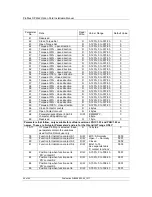
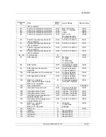
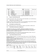
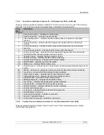
In order that a replacement can be easily introduced in the event of a device failure it is very important
to record and keep safe all the settings made for the variable registers. The table lists all the registers
that must be checked and set up for each Profibus Module on a network. The data should be recorded
for each module.
GSD accessed Parameters
Device Address:
Parameter
No.
Description
Setting
Notes
1
Limited Range Position Minimum
2
Limited Range Position Maximum
3
Deadband
4
Hysteresis
5
Slow Mode Range
6
Motion Inhibit Time
7
Manual Movement Travel
8
Valve Jammed Time
9
Watchdog Timeout
10
Action on Loss of Comms
11
Comms Lost Position
12
Comms Fault Timer
13
Aux Input Mask
14
ESD DI-4/Net Disable
15
FR/SR mode and Simple/RedCom redundancy
16
Part Stroke position
17
Part Stroke Limit and timeout
18
Actuator Type
Acyclic Communications accessed Parameters
Parameter
No.
Description
Setting
Notes
20
Actuator Tag data
25
Permit GSD Parameterisation
38
Multiport Number of ports
39
Multiport Active ports
68
Parameterisation date
Note:
Make a note of all changes to register settings to ensure that, in the case of a failure,
the replacement device can be swiftly set to the correct values.

