Profibus DP Mk2 Option Card Installation Manual
18 of 84
Publication PUB088-005-00_1017
3.6 Replacing or Fitting a Profibus DP (Mk2) Option Card
The PFU should be replaced or fitted only in a suitable environment. The actuator must be made
electrically safe before opening any covers and in the case of an IQ or IQT it is advisable to
disconnect the internal battery.
Suitable anti-static precautions should be taken, as the actuator circuitry contains static-sensitive
components.
The electrical housing cover should be removed and the existing PFU carefully unplugged from its
main connector. The Interface card will be attached to the Main PCB mounting ring by two screws,
which may be T20. Once removed from the main connector the wiring loom connectors should be
removed. The replacement board is fitted in the reverse order to removal. The wiring harnesses are
polarised so that only the correct one will fit its mating part on the circuit board.
If the operation is to fit a PFU for the first time then the necessary wiring looms must be added to the
internal wiring harness of the actuator. The actuator wiring diagram shows the connectors and
harnesses used. The wiring harnesses are fitted inside the actuator before attempting to fit the PFU.
Once the looms are in place connect them to the PFU, then fit the PFU to the actuator main board
connector.
Once the module is fitted the actuator should be re-assembled and, in the case of the IQ or IQT, the
battery replaced.
The PFU must not be split between its Network Interface Card and the Interface card. Only complete
assemblies should be fitted or exchanged.
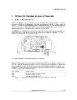
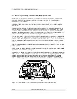
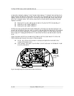
If at any time it is necessary to reset the interface card used for the Q and the Skil / EH to its supplied
default values, the Network Interface card should be removed and a shorting link applied to LK1. The
Interface card must then be put back in the actuator and the mains power cycled. The Network
Interface card must then be re-assembled onto the interface board and the pair refitted into the
actuator. LK1 is usually used as a mechanical connection link between the top and bottom boards.
SK5
SK7
SK10
EPROM
SK1
SK2
SK8
LK1
Fig 11: The Profibus Mk2 Interface card showing the position of LK1 (NIC removed)
LK1


