MDR-42
Technical Data
ROTEC technology
- 36 -
9.4.2.15. Inverter support INV
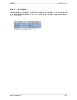
A backlight inverter with no heave load can be driven by the rBaseETX board. Via the CHILI interface the
dimming voltage vor the backlight inverter can be controlled. The BL_ON signal at the connector is driven from
ETX module. The BL_ON signal can be additional controlled by the two jumpers BL_FIX_ON and BL_ENABLE.
Please refer for understanding the following state table. With the IO-1-7 line from the GPIO the backlight can
be enabled or disabled. This is useful for dark boot phases. In the table X means state don't cares, L means
logical low level and H means logical high level. Please remark that the BL_ON_ETX signal which comes directly
from ETX board is inverted, e.g. a low level at this line means backlight is on.
BL_ON_ETX BL_FIX_ON BL_ENABLE BL_ENABLE (GPIO) BL_ON
X
closed
X
X
H
H
open
open
X
L
L
open
open
X
H
X
open
closed
IO-1-7 = L
L
H
open
closed
IO-1-7 = H
L
L
open
closed
IO-1-7 = H
H
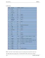
Table 20: Function matrix BL_ON
PIN
Description
Type
1
Vcc +12V
PWR
2
Vcc +12V
PWR
3
Vcc +12V
PWR
4
Vcc +12V
PWR
5
BL_ON
OUT
6
Brightness
Analog 0-3.3V
7
GND
PWR
8
GND
PWR
9
GND
PWR
10
GND
PWR
Table 21: Inverter Pin assignment
Summary of Contents for MDR-42
Page 1: ...MDR 42 Ruggedized POI PC Display User Manual you ROTEC ...
Page 2: ......
Page 14: ...MDR 42 Important Safety Information ROTEC technology 12 ...
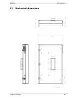
Page 28: ...MDR 42 Technical Data ROTEC technology 26 9 3 Mechanical dimensions ...
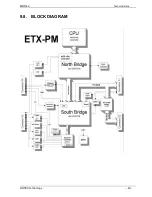
Page 42: ...MDR 42 Technical Data ROTEC technology 40 9 8 BLOCK DIAGRAM ...

