8
Attaching Cables
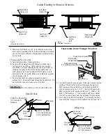
Sheave
Spacer
Sheave
Nut
Spacers
Sheave
Pin
Sheave
Yoke End
Sheave
Cover
Yoke
End
Spacers
Pinetree
Retainer
Viewed from above
Jam Nut
Column Top
Plate
5
/
16
" Machine Screw
8. Adjust Cable:
Adjust all cables with lift fully lowered. Loosen cable jam nut.
Tighten adjusting nut on cable stud on top of column until
yoke end is raised
1
/
4
”. Back off adjusting nut one (1) turn.
Tighten jam nut. Do this for all four (4) cables. See Fig. 13.
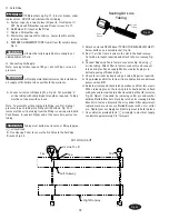
9. Power Unit:
A. Align Air Valve Bracket with holes in right side of
column bracket, Fig. 16.
B. Put four
5
/
16
” x1-
1
/
2
” lg. hex. bolts through holes in column
bracket, using push-nuts to hold in place. When using 3Ø
Control Box with push button, position mounting bracket to
the rear of the power unit bracket and attach using two (2) of
the
5
/
16
”-18NC x 1 1/2” HHCS, Fig. 16.
C. Mount power unit, with motor up, to the column bracket and
install four
5
/
16
” lock washers and nuts.
D. Run hydraulic hose from runway through slot in side of
runway to power unit output port, Fig. 17. DO NOT use Teflon
tape on hydraulic hose connections. Install and hand tighten
elbow to pump until O-ring is seated and elbow should be
oriented downward at approximately 45°,Fig. 17. Tighten
locknut to 35-40 ft. lbs.
E. Install enclosed capacity label on power unit, Fig. 17.
10. Electrical: Have a certified electrician run 230 volt
single phase 60 Hz. power supply to motor, Fig.18 and 19. Size
wire for 30 amp. circuit. See Motor Operating Data table.
Numbers 5 & 6
Refer to
Parts
Breakdown
Fig. 13
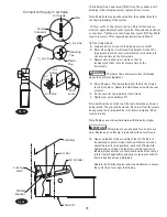
IMPORTANT
Cables must fit in slack cable arm rollers, Fig.15
Fig. 15
Fig. 14
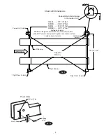
Right Rear
(#4)
Left Front
(#1)
Left Rear
(#3)
Roping Diagram
Right Front
(#2)
Cable in Slack Cable Arm Rollers
Locking Latch
Slack Cable Arm Roller
Cable
Summary of Contents for RFL25
Page 14: ...NOTES ...
Page 15: ...NOTES ...


