4
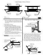
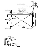
Fig. 8
Fig. 7
5. Columns:
Note: Columns are not interchangeable. They must be set at their
respective corner of the lift. Column double return bend is always
to inside of lift, Fig. 9. Place the power unit column at the left
rear corner of the lift. The point where the hydraulic hose passes
through side of left runway should be visible from this corner.
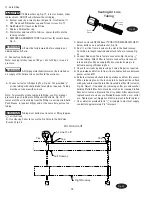
Insert alignment stud through hole in yoke end and thread into
base plate of column, Fig. 8. Repeat for other columns.
Fig. 8a
IMPORTANT
Use Yoke Spacer As Shown To
Maintain 5/16" Of Gap From End
Of Yoke To Front Of Latch Bar.
Be Sure To Remove Spacer
After Installation.
1
2
Ears Of
Spacer
Tee
Left Runway
Right
Runway
Air Line in Runway
Air Line To
Lift
Tee
Tee
Alignment Stud
5
/
16
" REF. Between Yoke End and Latch Bar
Yoke Assembly
Alignment Stud
Latch Bar
Column
IMPORTANT
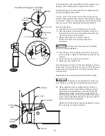
The yoke/column alignment studs MUST be used
for proper centering of columns to yokes, Fig. 8. A gap of
5
/
16
” must be maintained between column and yoke.
See step 6 B. Note: It may be necessary to remove Plastic Slider
from Column Stop on yoke end, Fig. 10, before aligning yoke
in column. After yoke is in column, reinstall Plastic Slider and
secure with
5
/
16
” button head screw.
Summary of Contents for RFL25
Page 14: ...NOTES ...
Page 15: ...NOTES ...


