11
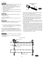
1/4” Flat Washer
1/4”-20NC x 1/2” HHCS
1/4” Star Washer
Note:
The contactor in the control box has a 480V coil.
For installations where the electric supply is 230V,
the coil must be replaced with the extra 230V coil
shipped with the control box. For 575V electric
supply, the coil must be replaced with the extra
575V coil shipped with the lift.
Fig. 20
Fig. 21
10. 3ø Control Box Installation:
A. Attach Control Box to Bracket using (4) 1/4”-20NC x 1/2”
HHCS, (4) 1/4” Flat Washers, and (4) 1/4” Star Washers. Fig.
20.
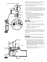
B. Route cord through strain relief on motor and connect per
table on top of page.
T1
T2
T3
U2
V2
W2
W1
V1
U1
575V 60 Hz. 3Ø
Three Phase Power Unit
MOTOR OPERATING DATA TABLE - THREE PHASE
LINE VOLTAGE RUNNING MOTOR VOLTAGE RANGE
208-240V 50/60Hz.
197-253V
400V 50Hz.
360-440V
440-480V 50/60Hz.
396V-528V
575V 60Hz.
518V-632V
L1
L2
L3
L1
L2
L3
208-240V
50/60Hz. 3Ø
440-480V 50/60 Hz. 3Ø
380-400V 50 Hz. 3Ø
Current Pin Layouts
Older Pin Layouts
W2
U2
V2
W2
U2
V2
U1
V1
W1
U1
V1
W1
T7
T1
T8
T2
T9
T3
T4
T5
T6
L1
L2
L3
T7
T4
T1
L1
T8
T5
T2
L2
T9
T6
T3
L3
208-240V
50/60Hz. 3Ø
440-480V 50/60 Hz. 3Ø
380-400V 50 Hz. 3Ø
Summary of Contents for RFL25
Page 14: ...NOTES ...
Page 15: ...NOTES ...


