


Rotar Giga 75-100 - Cod.197AA3900 - Rev.03 - 05/2007
14
14
14
14
14
12
Rotar 75
Rotar 100
P max. 8 bar
56 Hz
63 Hz
P max. 10 bar
55 Hz
62 Hz
1
2
3
4
H
G
I
L
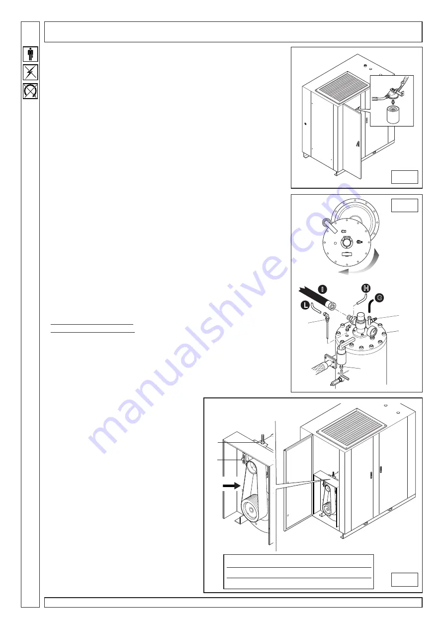
MAINTENANCE
AFTER THE FIRST 2,000 OPERATING HOURS AND THEN
EVERY 4,000 OPERATNG HOURS
Change OIL FILTER (fig.10)
•
Change the filter at any oil change with the oil separator tank not under
pressure. Always bleed all air off the cock (1) (see fig. 11).
•
Open door (E) (see fig.7). The oil filter is inside the middle stand, as shown
in the figure.
•
Undo the filter with the proper tool. Replace with a new filter. Always apply a
film of oil on filter edge and gasket before tightening.
Change OIL SEPARATOR FILTER (fig.11)
•
Open door (F) (see fig.7) and bleed all air off the tank through cock (1).
•
Disconnect tubes G, H, I and L.
•
Fully undo fitting (2) and remove copper drain tube.
•
Undo and remove screws (3).
•
Turn screw (4) anti-clockwise with a hex. wrench, until lifting oil separator
cover by about 0.5 cm.
•
Manually turn the cover to reach tank inside.
•
Remove oil separator filter (using a proper tool) and replace with a new
filter. Also replace the two seal rings and make sure they are properly seated.
EVERY 10000 HOURS
DRIVE BELT tension (fig.12)
To perform this check you need a special measurement instrument that that
provides a precise indication of the level of tension of the belt by means of a
frequency measurement.
Proceed as follows:
•
Open the door (D) (see fig.7).
•
Bring the microphone of the measurement instrument up to the belt at the
point indicated with “test” (about halfway) and strike the belt with a spanner.
•
Read the value detected by the instrument and if it is different from the
values indicated on the table, adjust the tension:
Higher value = belt too tight
Lower value = belt too loose
•
Loosen screws A to allow the attachment plate on which the screw unit is
fixed to slide, and use adjusting nut B to adjust the tension.
Turn the nut anti-clockwise to increase tension and clockwise to reduce tension.
Re-tighten screws A and check the frequency value; if necessary, repeat the
operation until the desired value has been reached.
EVERY 20000 HOURS
Replace the DRIVE BELT (fig.12)
Proceed as follows:
•
Open the door (D) (see fig.7) and remove the
protective panel of the belt/pulley compartment.
•
Loosen screws A to allow the attachment plate
on which the screw unit is fixed to slide.
•
Loosen nut B until the belt is completely
relaxed and remove it.
•
Fit the new belt and tighten it as described in
the previous section.
Also replace
•
Compressor seal ring
•
Tank safety valve
10
11
A
B
Test
Summary of Contents for Giga 100
Page 2: ......


