background image

Rotar Giga 75-100 - Cod.197AA3900 - Rev.03 - 05/2007

GB

15

15

15

15

15

2

3

1

MAINTENANCE

13

EVERY 15,000 OPERATING HOURS

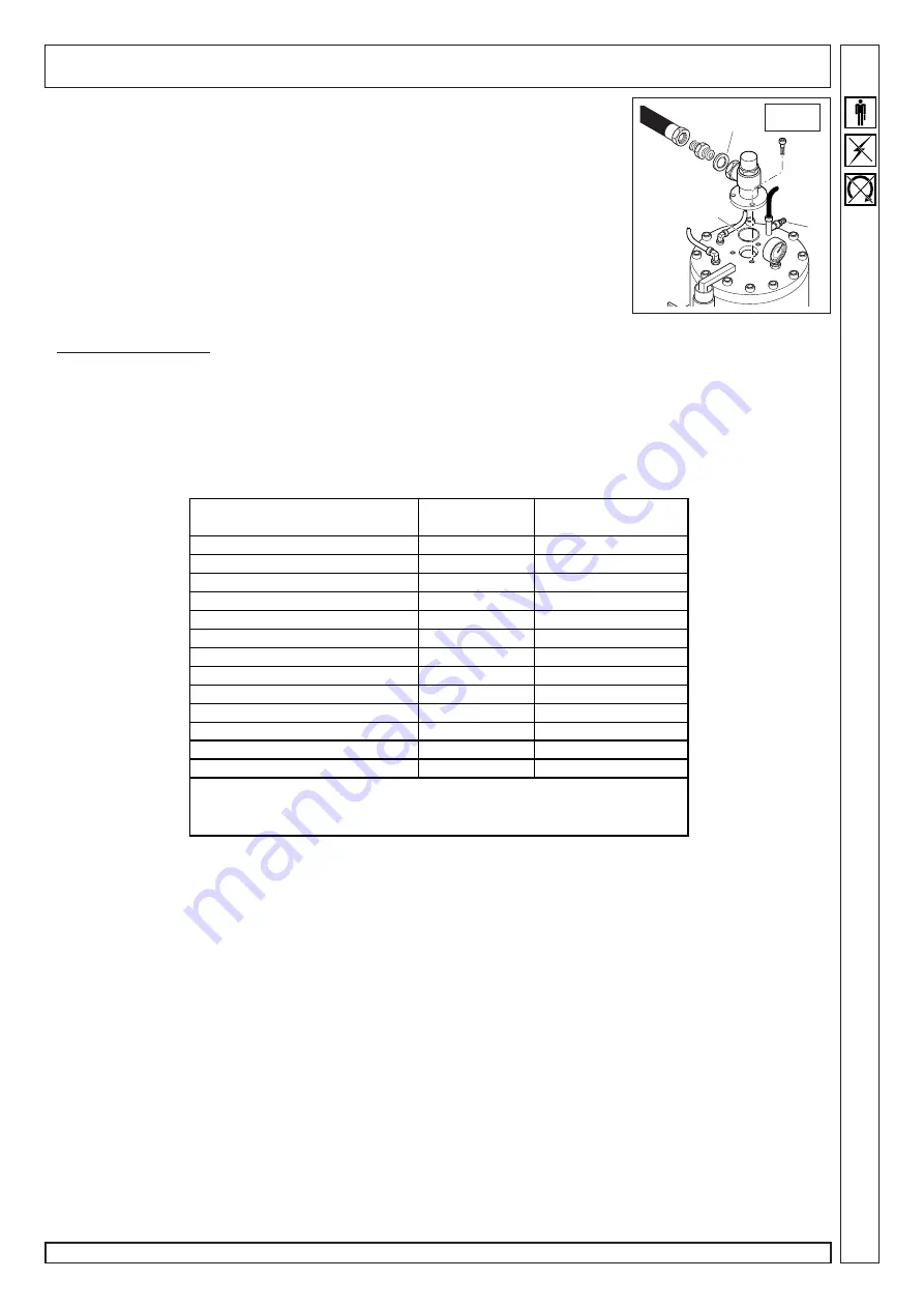
MIN. PRESSURE valve (fig.13)
Open door (F) (see fig.7) and bleed all air off the tank through the cock (1).
Replace gaskets (2) and (3)

.

SERVICE TABLE - WARNING

Oil is an essential factor. When using an oil type which is different from the recommended one - RotEnergy Plus -  some service

intervals must be changed. Please refer to table.

In any case, a different oil MUST be used ONLY when oil is fully changed. NEVER MIX DIFFERENT TYPES OF OIL TOGETHER.

Never top up with a different type of oil.

EXHAUSTED OIL IS HIGHLY POLLUTANT! Dispose of exhausted oil in compliance with current laws.

Used oil 

RotEnergy Plus

Different compatible oil 

(see table)

Service description

Operating hours

Operating hours

Check and top up oil level

300

300

Clean intake filter and prefilter

500

500

Grease the electric motor bearings

4000

4000

Replace intake filter element 

2000

2000

Replace oil filter

4000

4000

Replace oil separator filter

4000

4000

Change oil

8000

4000

Check driving belt tension

10000

10000

Check min. pressure valve

15000

15000

Replace driving belt

20000

20000

Replace  compressor seal ring

20000

20000

Replace tank safety valve

20000

20000

Compatible oils: SHEEL Corena D46 - BP Energol HLP 46 - MOBIL  D.T.E. 
MEDIUM - AGIP Dicrea 46 - CASTROL  Aircol MR46 - ESSO Univis 46 -                                              
IP Veretum Oil 46 - FINA Eolan R046

Summary of Contents for Giga 100

Page 1: ...Rotar Giga 75 100 Cod 197AA3900 Rev 03 05 2007 GB use maintenance MANUAL Rotar Rotar Rotar Rotar Rotar Giga 75 100 Giga 75 100 Giga 75 100 Giga 75 100 Giga 75 100...

Page 2: ......

Page 3: ...1 oil drain tube no 1 door key no 1 user s guide CONDITION OF THE MACHINE WHEN SUPPLIED Every compressor is shop tested and delivered ready to be installed and to be set at work The oil used is RotEn...

Page 4: ...ce and maintenance carried out so far SYMBOLS USED IN THE MANUAL Some symbols are used to highlight danger situations give recommendations or information These symbols are usually positioned next to t...

Page 5: ...CE plate Always follow the maintenance schedule specified in the user s guide WHAT NOT TO DO Do not touch inner parts and pipes as they are very hot during compressor operation and stay hot for a cer...

Page 6: ...tion of the machine Open the access doors and check all inner parts visual check Dispose of the packaging in compliance with the current waste disposal regulations PLACEMENT fig 2 The room chosen for...

Page 7: ...the compressor heat energy as auxiliary heating unit These pipes should not be longer than 4 m Otherwise an auxiliary fan should be installed on the outlet side POWER CONNECTION Proceed to power conne...

Page 8: ...takes you to the menu of operating parameters In certain cases a password is required in order to access the modifications Use the buttons to scroll the menu 0 Control unit ID service password selects...

Page 9: ...ssure assistance password enabling this parameter the visualisation of the pressure and respective alarms is maintained but the control of the start of the compressor takes place using an external pre...

Page 10: ...t verify the cause and then press the RESET button XX Emergency button Alarm tripped when the emergency button is pressed which blocks compressor operation To silence the alarm first reset the emergen...

Page 11: ...filter replacement is required bearing lubric indicates the hours remaining until lubrication of the bearings is required oil filter h indicates the hours remaining until oil filter replacement is re...

Page 12: ...il is returned to filter 11 through tube 10 From filter 11 oil reaches compressor 3 through tube 12 Oil is mixed with sucked air to form an air oil mixture that provides sealing and lubrication of com...

Page 13: ...light for possible cuts replace element if any CHANGE THE AIR FILTER ELEMENT EVERY 3000 HOURS Undo retaining screws 3 from support panel 4 and remove prefilter Wash with water and soapy solution Fully...

Page 14: ...ion fig 12 To perform this check you need a special measurement instrument that that provides a precise indication of the level of tension of the belt by means of a frequency measurement Proceed as fo...

Page 15: ...STED OIL IS HIGHLY POLLUTANT Dispose of exhausted oil in compliance with current laws Used oil RotEnergy Plus Different compatible oil see table Service description Operating hours Operating hours Che...

Page 16: ...emove and clean the intake regulator Oil mist separator filter clogged Replace the oil mist separator filter Line cock closed Open the cock Minimum pressure valve blocked Check and clean the valve if...

Page 17: ...r no Ambient temperature C Noise level 1 m dB A Max compression temperature C Safety valve setting bar Separator pressure switch setting bar 8 9 10 9 8 9 10 9 Start up pressure switch setting bar Moto...

Page 18: ...12 13 14 15 15 15 15 16 17 18 19 20 24 L22 L12 2 L31 L11 FU1 3 3 5 6 8 10 HL YV BULBO TERM THERM PROBE YV 5 25 AUTO DRAIN BULBO TERM THERM PROBE 3 3 PL1 PL2 10 8 6 5 12 13 22 021 ST2 BP V P V 021 22 2...

Page 19: ...n pressure switch SA Radiator fan emergency control BP Line pressure transducer ST1 Screw delivery temperature probe ST2 Outlet air temperature probe D Electronic controller YV Solenoid valve M1 Upper...

Reviews: