


Rotar Giga 75-100 - Cod.197AA3900 - Rev.03 - 05/2007
6
6
6
6
6
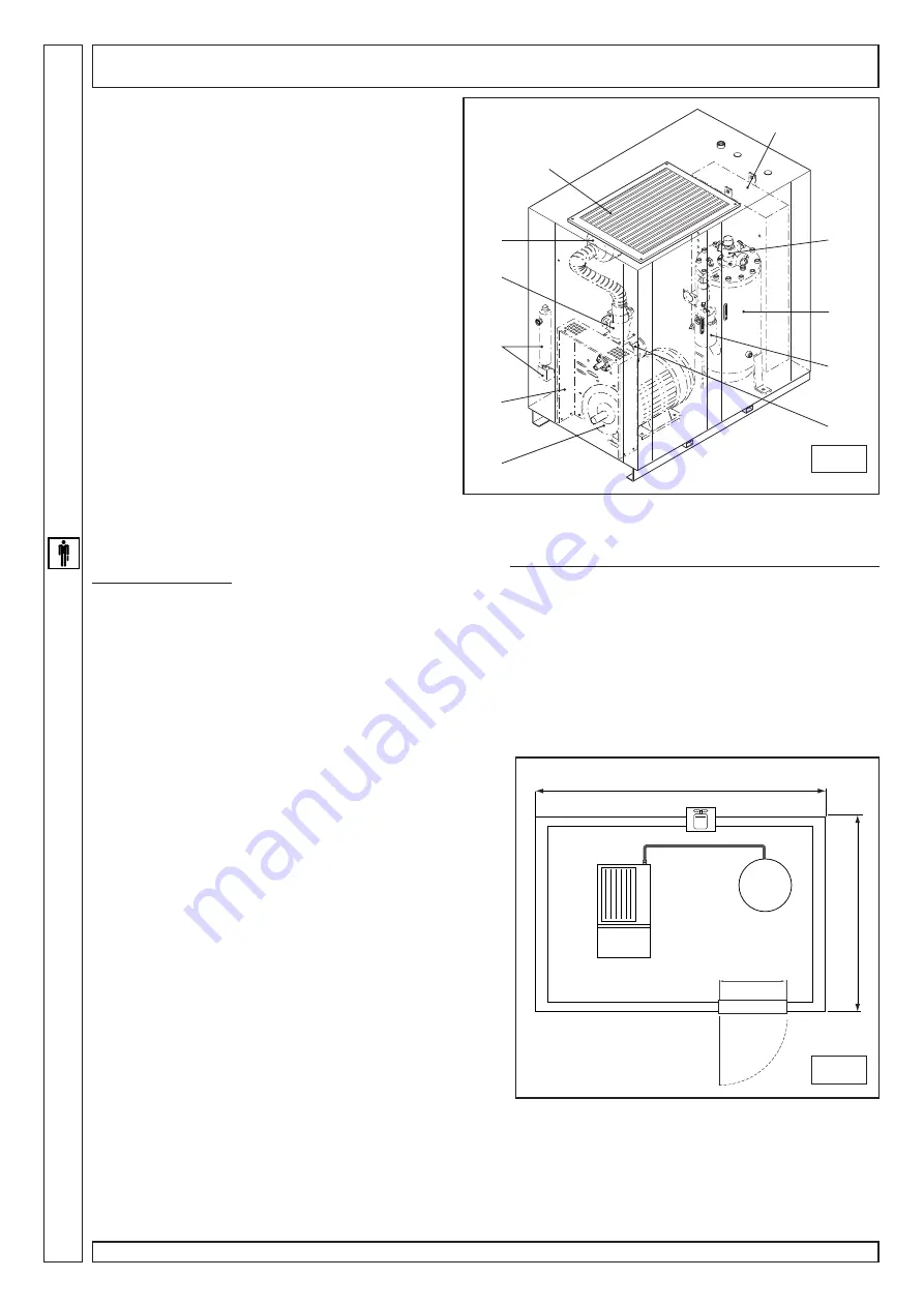
150 cm (min)
600 cm (min)
350 cm (min)
h min = 350 cm
1
2
3
4
5
6
7
8
9
10
11
COMPRESSOR DESCRIPTION (fig.1)
The compressor essentially consists of:
1)
Condensate trap / condensate drain (Autodrain)
2)
Screw/motor support plate
3)
Motor
4)
Suction regulator
5)
Air intake filter
6)
Air-oil radiator
7)
Electric box /control panel
8)
Min. pressure valve
9)
Oil separator tank/oil separator filter
10) Oil filter
11) Screw compressor
UNPACKING AND HANDLING
The compressor is usually shipped to a Customer into a special packing so to protect the compressor against transport damages.
As the compressor is very heavy (see “technical features” table), it must be lifted only by means of suitable capacity driven by
specialized personnel.
Compressor base has slots, whereas compressor top has four anchoring points for eyebolts in case the compressor needs to
be lifted from the top by crane or hoist.
Do not stand within fork lift truck working area and keep safety distance.
Perform the following after moving the compressor to the installation place:
• Unpack the compressor. Wear protective gloves and use suitable tools (follow instructions on the crate)
• Check the (outer) good condition of the machine.
• Open the access doors and check all inner parts (visual check)
• Dispose of the packaging in compliance with the current waste disposal regulations.
PLACEMENT (fig.2)
The room chosen for the installation of the compressor should
meet the following requirements and comply with current safety and
accident prevention regulations:
A)
low percentage of dust suspended in air,
B)
Proper room ventilation and size that allow room temperatu-
re (5°C ÷ 50°C) to be maintained - with the machine running.
Min. air intake opening: 2 sq. m
C)
In the event of inadequate hot air discharge, fit three or more
exhaust fans as high as possible.
Exhaust fan “4,000 cu. m/h” part no. 020042000
•
The condensate is a polluting mixture and should not be
disposed of into the sewage system or wasted in the environment.
The sump should be equipped either with a valve and a removable
container or connected to a suitable piece of equipment (oil-water
separator, part no. 048203000).
Dimensions shown in fig. 2 are indicative. It is recommended to
comply with given indications.
INSTALLATION
•
Position the machine at the final place of installation. Make
sure it is stable and leave at least 90 cm between the machine
and the wall so as not to obstruct proper air flow to the fan.
Position the air tank. Connect the compressor and tank using the
supplied delivery hose.
Do not fit check valves between compressor and tank.
INSTALLATION
1
2
Summary of Contents for Giga 100
Page 2: ......


