Ropex RESISTRON RES-5009 User Manual Download Page 51

Device functions

Version 1

RES-5009

Page 51

7

901

4.66

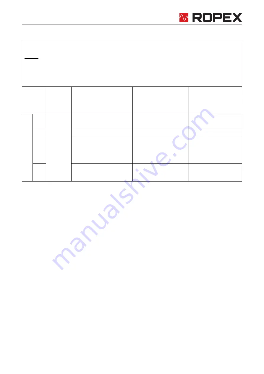
Line voltage/synchronising 
signal missing

Replace device

Replace device

913

Triac defective

Replace device

Replace device

914

Int. error, device defective

Replace device

Replace device

915

916

917

Incorrect slide switch for 
alarm output

Check slide switch

Check slide switch

918

Part 1 of 3: Error messages (faults)

NOTE:

 The specified error messages are output as faults:

• Actual value output displays constant error voltage

• Alarm LED lights up continuously

• Alarm relay is active

Error no.

Actual 

value 

outp. 

Voltg. [V]

Cause

Measure during initial 

startup

Measure during 

machine operation, 

heating element not 

changed

Summary of Contents for RESISTRON RES-5009

Page 1: ...atic optimisation AUTOTUNE Automatic configuration of the secondary voltage and current range AUTORANGE Automatic phase correction AUTOCOMP Automatic frequency adaptation Booster output standard Analogue output 0 10 VDC for ACTUAL temperature Additional 24 VDC control signals for START 0 setpoint 0 and START 1 setpoint 1 Alarm function with error diagnosis Heating element alloy and temperature ran...

Page 2: ...Mains connection 16 7 4 Line filter 17 7 5 Current transformer 17 7 6 Wiring diagram standard 19 7 7 Wiring diagram with booster connection 20 8 Startup and operation 21 8 1 Device view 21 8 2 Device configuration 21 8 3 Switch for activating the CAN terminating resistor 24 8 4 Selection of CAN protocol 24 8 5 Burning in and changing the heating element 25 8 6 Startup procedure 26 9 Device functio...

Page 3: ... 15 TCR calculator 72 10 16 Signals START 0 and START 1 73 10 17 Date and time in CANopen 73 10 18 CANopen Time stamp object 74 10 19 CANopen states 74 10 20 Transmission of multi byte elements with CANopen 74 10 21 CANopen Timing values 74 11 ROPEX CAN 75 11 1 Setting the baud rate 75 11 2 Setting the CAN identifier 76 11 3 ROPEX CAN LEDs 76 11 4 ROPEX CAN protocol 77 11 5 Receiving CAN messages ...

Page 4: ...Page 4 RES 5009 Version 1 ...

Page 5: ...user in the vicinity of the RESISTRON Temperature Controller In order to ensure safe operation please observe the safety and warning information included in the operating instructions 2 2 Drawings and illustrations The drawings and illustrations in these operating instructions are exemplary Many details are presented in a sim plified manner 2 3 Copyright All contents in particular texts photograph...

Page 6: ...ply to information units smaller than the section related warning notices Embedded warnings are structured as follows SIGNAL WORD Instructions to avoid a dangerous situation 3 1 4 Meaning of the hazard symbols The hazard symbols in the warning notices have the following meanings Signal word Importance Imminent danger Consequence Death or serious injuries Possibly imminent danger Consequence Death ...

Page 7: ...derstood the operating instructions important information on the correct handling of the product WARNING Danger to life and danger of serious physical injuries as well as property damage if all warnings regulations and information are not followed Strictly follow all warnings regulations and information in these operating instructions WARNING Danger to life and risk of serious physical injuries as...

Page 8: ...significantly in terms of performance and physical dimensions All information provided by us in connection with the line filter is merely intended as a guide and is based on a typical measuring setup It serves to demonstrate that compliance with the EMC directive can be achieved by using a line filter that is suitable for the overall system The line filter and current transformer must however be d...

Page 9: ...il TCR 1100 ppm K The setting or coding of the RESISTRON Temperature Controller has to be carried out according to the temper ature coefficient of the heating element used The temperature coefficient must be taken from the ROPEX application report and must be set accordingly More information High resistance heating elements such as NiCr 80 20 are not suitable for an operation with a RESISTRON Temp...

Page 10: ...system In order to avoid malfunctions only the original ROPEX current transformers or ROPEX monitoring current trans formers may be used The current transformer may be operated only if it is correctly connected to the RESISTRON Temperature Con troller See Chapter Start up The safety related information in the Mains connection chapter must be observed External monitoring modules can be used to incr...

Page 11: ...he application report If you cannot judge whether your material can be sealed or what cycle rate is possible we can also create sealing samples for you We will then use our system and your material to check the possibility for sealing and incorporate the findings into the application report In this case you are welcome to contact info ropex de Your request will then be passed on to the application...

Page 12: ...AL temperature of the heating element is output through the CAN interface and through an analogue output 0 10 VDC The real heating element temperature can be visualised on an external display instrument e g ATR x or via the operating unit of the machine controller The RESISTRON Temperature Controller RES 5009 has an integrated error diagnosis which checks both the external system heating element w...

Page 13: ... also section 4 Requirements for the functioning of the control system on page 9 7 1 Installation sequence Proceed as follows during mounting and installation of the RESISTRON Temperature Controller RES 5009 1 Switch off line voltage and 24 VDC power supply verify lack of voltage 2 Installation of the RESISTRON Temperature Controller in the switching cabinet on a TS35 top hat rail in accordance wi...

Page 14: ...ers must be provided for the controller and the welding application ROPEX application report The circuit breaker must be located in the immediate vicinity of the device In the ROPEX application report the smallest possible specification for this circuit breaker is specified based on the calculated currents If the protective device is dimensioned differently the current carrying capacity of the com...

Page 15: ... and can make the system prone to errors in the long term Line Impulse transformer Current transformer PEX W4 W5 U prim 1 Heatsealing band R f T U sec 2 A F Avoid long cables Heatseal element with coppered ends Use heatseal bands with suitable temperature coefficient 20 mm clearance if several controllers installed on one top hat rail No additional resistance in secondary circuit Dimension transfo...

Page 16: ...crease machine safety by switching off the load on all poles in the event of a fault e g in combination with the ALARM output of the RESISTRON Temperature Controller Dimensioning ROPEX application report I1max for Ka and Kb Impulsetransformer Design according to EN 61558 or UL 5058 isolating trans former with reinforced insulation Ground core CAUTION Use only single chamber design Power ED number ...

Page 17: ...ctions in the section 7 3 Mains connection on page 16 with regard to cabling must be complied with Example drawing for LF 06480 7 5 Current transformer The current transformer PEX W4 W5 appropriate for RESISTRON Temperature Controller is part of the control system The current transformer may be operated only if it is correctly connected to the temperature controller section 7 3 Mains connection on...

Page 18: ...hat rail measuring 35 x 7 5 mm or 35 x 15 mm in accordance with EN 60715 If the high current line cannot be conducted through the opening provided due to the diameter an HCB 1 high current rail must be used Snap on for DIN rail 35 x 7 5mm or 35 x 15mm EN 60715 terminal block terminal wires 14 60 24 75 14 23 28 26 39 12 ...

Page 19: ...SHLD NC CAN_GND NC SUPPLY CAN_H CAN_L R Current transformer Impulse transformer LINE 11 9 10 8 4 3 2 1 IR UR 15 Heatsealing element sec U2 prim U1 twisted Line filter ALARM OUTPUT max 30 V Ground Must be grounded externally to prevent electro static charging 17 C ATR _ ANALOG OUTPUT 0 10 VDC 14 13 12 6 Shield START 1 Setpoint 1 with 24 VDC signal START 0 Setpoint 0 with 24 VDC signal 7 16 18 BOOST...

Page 20: ...GND NC SUPPLY CAN_H CAN_L R Current transformer Impulse transformer LINE 11 9 10 8 4 3 2 1 IR UR 15 Heatsealing element sec U2 prim U1 twisted Booster 2 4 IN OUT 1 3 Line filter twisted Length max 1 m NC NC ALARM OUTPUT max 30 V Ground Must be grounded externally to prevent electro static charging 17 C ATR _ ANALOG OUTPUT 0 10 VDC 14 13 12 6 Shield START 1 Setpoint 1 with 24 VDC signal START 0 Set...

Page 21: ...d in the current range from 30 A to 500 A If voltage and or current is outside the allowed range a detailed error message is output by the controller section 9 15 Error messages on page 49 For secondary currents I2 less than 30 A the secondary high current line must be guided 2 times or several times through the transformer PEX W4 or PEX W5 ROPEX application report NOTE The controller must be swit...

Page 22: ...d alloys can be set through the ROPEX visualisation software section 9 8 USB interface for visualisation software ROPEXvisual on page 45 0 5 1 2 3 4 6 7 8 9 0 Factory settings 0 5 1 2 3 4 6 7 8 9 AUX SWITCH POS 1 0 4 5 8 9 TEMP RANGE 300 C 300 C 500 C 500 C 300 C PC CONFIGURATION 780ppm K 1100ppm K L A20 1100ppm K A20 780ppm K 3500ppm K L TEMP COEFFICIENT Switch position 0 1 4 5 8 300 C 300 C 500 ...

Page 23: ... of alarm in com bination with contactor Kb to switch off the load in the event of a fault As a result the interrup tion of the line cable breakage between the alarm relay of the RESISTRON temperature controller and the alarm signal relay will be monitored Alarm relay contact opened by alarm Alarm relay contact closed by alarm factory setting 0 5 1 2 3 4 6 7 8 9 SWITCH POS 1 0 4 5 8 9 TEMP RANGE 3...

Page 24: ...ols The selection is made via the DIP switch CAN CANopen 3 2 1 4 ON 5 6 TERMINATION 0 5 1 2 3 4 6 7 8 9 SWITCH POS 1 0 4 5 8 9 TEMP RANGE 300 C 300 C 500 C 500 C 300 C PC CONFIGURATION 780ppm K 1100ppm K L A20 1100ppm K A20 780ppm K 3500ppm K L TEMP COEFFICIENT CAN termination resistor inactive factory default CAN termination resistor active ON OFF 3 2 1 4 ON 5 6 0 5 1 2 3 4 6 7 8 9 SWITCH POS 1 0...

Page 25: ...ng and renewed zero calibration AUTOCAL the heating element is burned in and the change of resistance is stabilised The heating element can now be used Burn in process It is carried out whilst the tool is open 1 Carry out AUTOCAL so that the controller calibrates itself to the cold resistance of the heating element 2 Heat the heating element to 250 C but at least 50 C above the application related...

Page 26: ...ement If the new heating element has another specification e g heating element cross section alloy the application must be checked ROPEX application report If this specification was not taken into account in the application report the application report must be updated in accordance with the new requirements 8 6 Startup procedure Observe here section 2 General information on page 5 and section 5 1...

Page 27: ...R x must be on the Z marking If the zero calibration is not successful the AL bit Alarm active is set and the red ALARM LED blinks slowly 1 Hz Then the configuration of the controller is not correct section 8 2 Device configuration on page 21 ROPEX application report After the device configuration is correct perform the zero calibration again 10 After successful zero calibration specify a defined ...

Page 28: ...ent While changing the heating element proceed as per section 8 5 Burning in and changing the heating element on page 25 Continue with chap 8 6 1 item 5 to item 11 WARNING Pay attention to correct alloys dimensions and copper coating of the new heating element to avoid malfunctions and overheating ...

Page 29: ...uested but function is blocked START is carried out ALARM red Configuration error AUTOCAL not possible Controller incorrectly cali brated carry out AUTOCAL Error chap 9 15 ERR green LED red LED BUS POWER RUN 24 V POWER green LED green LED Lights up or blinks according to the CAN protocol used Lights up or blinks according to the CAN protocol used Lit if internal power supply for CAN interface is O...

Page 30: ... CANopen CAN masters the parameter data cannot be changed during operation Adjustment of the calibration temperature to the current ambient conditions in the machine is therefore not possible The calibration temperature with the appropriate setting in the parameter data section 9 4 4 Variable cali bration temperature on page 38 can therefore be specified at every zero calibration through the input...

Page 31: ... bit 1 the AUTOCAL LED blinks quickly 4 Hz Further information CANopen section 10 7 6 Control information on page 67 AC bit ROPEX CAN section 11 5 Receiving CAN messages on page 77 Address 0004h and value 5d 9 2 2 Start ST With the start request ST bit the device internal target actual comparison is enabled and the heating element is heated up to the set SETPOINT temperature This takes place eithe...

Page 32: ...suring pulses any more In the error diagnosis only errors no 5 and 7 201 203 901 913 are evaluated and output The actual value is no longer updated The most recent value valid before activation of the measurement pause MP bit is output After deactivating the measurement pause measuring pulses are immediately generated again all error messages are evaluated and the actual value is updated The measu...

Page 33: ...tly like older models that do not yet support any different calibration data sets While the channel can be switched during performance of the AUTOCAL function the controller works with the channel chosen at the start of the AUTOCAL function until the AUTOCAL function is completed The channel cur rently used by the controller is visible in the status information The selected channel is not stored r...

Page 34: ...mmands via the CAN interface as well as the 24 VDC signal START 0 have a higher priority 9 3 Output data Output data are the data transmitted from the RESISTRON Temperature Controller RES 5009 to the CANopen CAN master The output data contain the current actual value and all important information about the current status of the controller In case of alarm an exact error diagnosis can be performed ...

Page 35: ...The TO bit is set when the actual temperature is within the set temperature monitoring band If the actual tem perature is outside the monitoring band the TO bit is reset see following graphic The actual temperature is hereby evaluated independently of the control mode in contrast to the Temperature reached TE bit status bit 3 Active when Tact Tset with latch function A welding cycle begins with se...

Page 36: ...ture Controller RES 5009 does not perform a temper ature measurement during the regulation phase start request active This can occur when the actual value is larger than the setpoint value setpoint exceeded This can be used for example to evaluate whether measure ment interruptions occur during the heating impulse This would then be an indication of excessive temperature which can result in a bad ...

Page 37: ...e via write read accesses from the CANopen CAN master to the controller or queried by the controller The protocol specific access as well as the storage of parameter data is explained for CANopen in chapter section 10 7 2 Parameter data on page 63 and for ROPEX CAN in chapters and section 11 5 Receiving CAN messages on page 77 and section 11 6 Sending CAN messages on page 83 9 4 1 Temperature rang...

Page 38: ...ON Temperature Controller RES 5009 can be set For certain applications it can be necessary to lengthen the measurement impulse beyond the standard 1 7ms Further information CANopen section 10 7 2 Parameter data on page 63 CANopenobject 4006h ROPEX CAN section 11 5 Receiving CAN messages on page 77 address 0012h 9 4 6 Automatic phase correction AUTOCOMP In special welding applications it may be nec...

Page 39: ...his setting the AUTOCOMP function is automatically started after a successful execution of the AUTOCAL function While executing the function AUTOCOMP the OUTPUT LED blinks several times and the actual value output terminals 17 7 goes to 0 3 C i e approx 0 VDC Function AUTOCAL 1 t t 0 0 AUTOCAL Lights up t Off 2 0s AUTOCOMP AUTOCAL t Off LED Lights up OUTPUT LED Function AUTOCAL t t 0 0 AUTOCAL AUT...

Page 40: ...erature has not exceeded the lower tolerance band limit or has not dropped below the upper tolerance band limit the related error nos 309 310 are output and the alarm relay switches on A delay time 0 9 9 s can additionally be set in the parameter data After the lower tolerance band limit is exceeded the temperature diagnosis takes place only after the parametrised delay time has expired As a resul...

Page 41: ... parameterised via the parameter data as follows 1 Off factory setting The current ACTUAL temperature is always output in real time 2 On The same ACTUAL temperature that was current at the end of the last welding phase is output After the con troller is switched on the real ACTUAL temperature is displayed until the end of the first heating phase 3 2 Sec At the end of a welding phase the current AC...

Page 42: ...apsed measurement impulses will be generated again in order to determine the current ACTUAL temperature and to carry out error diagnoses This start up delay is 0 2 s by default and can be adjusted with the CANopen object 0x4014 Thus slower switching contactors can also be used The start up delay cannot be set in the ROPEX CAN protocol 9 4 11 Maximum measurement pause If the RESISTRON Temperature C...

Page 43: ...r RES 5009 is guaranteed for the tolerance range of the line voltage and 24 VDC supply voltage specified in section 15 Technical data on page 91 If the 24 VDC supply voltage falls below the permitted tolerance range the controller switches to a standby mode Welding processes and measuring impulses are no longer carried out If the input voltage is within the specified tolerance range again operatio...

Page 44: ...10 VDC 300 C ATR 3 or 500 C ATR 5 depending on the device configuration The correlation between the change in the output voltage and the ACTUAL temperature is linear RES 5009 Actual value output 7 17 0 V Temperature dis play E g ATR 3 0 10VDC Max 5 mA 0 300 C range 2 3 4 5 6 7 8 9 10 300 Temperature T C VDC Voltage U 60 90 120 150 180 210 240 270 1 20 ºC ZERO 0 66 V 0 500 C range 2 3 4 5 6 7 8 9 1...

Page 45: ...s sages on page 49 9 7 Booster connection The RESISTRON Temperature Controller RES 5009 has a connection for an external switching amplifier booster as standard The connection of an external switching amplifier at the terminals 15 7 is required at high primary currents constant current 5 A impulse current 25 A The switching amplifier must be connected in accordance with section 7 7 Wiring diagram ...

Page 46: ...alisation soft ware ROPEXvisual The software and the documentation are available in the download area search term Visual 9 9 AUX interface Internal interface for diagnosis and maintenance The interface is currently not available 9 10 Total cycles counter From the time of delivery of the RESISTRON Temperature Controller RES 5009 the number of welding cycles performed ST bit 1 is stored in the contr...

Page 47: ...7 with the indication of date and time time stamp This enables a more precise assignment of error messages when analyzing problems for example The integrated clock can be set and read out through the ROPEX visualisation software section 9 8 USB inter face for visualisation software ROPEXvisual on page 45 or through services of the CAN interface A maintenance free capacitor is used for operation of...

Page 48: ...al is given in one of these states ACTIVE in the operating state lights up permanently A 3 CAUTION If the alarm relay is configured differently than in the factory setting section 8 2 3 Configura tion of the alarm relay on page 23 these statuses are inverted C Output of the error numbers over the CAN protocol If there is an error Alarm will be set active AL bit The error number is displayed in CAN...

Page 49: ...he actual value output Internally in the controller the error messages are differentiated in even more detail The 3 digit error numbers described in brackets are displayed via the CAN interface and with the ROPEX visualisation software section 9 8 USB interface for visualisation software ROPEXvisual on page 45 The error search can thus be performed even more effectively CAUTION In order to avoid i...

Page 50: ... Temperature too low leave the tolerance band Chap 9 4 7 Check the dimensioning of the pulse transformer Check heat removal through the sealing pro cess Verify application through sealing tests 308 Temperature too high leave tolerance band Chap 9 4 7 309 Temperature too low toler ance band not reached Chap 9 4 7 310 Temperature too high toler ance band not reached Chap 9 4 7 5 201 3 33 Line freque...

Page 51: ...e device 915 916 917 Incorrect slide switch for alarm output Check slide switch Check slide switch 918 Part 1 of 3 Error messages faults NOTE The specified error messages are output as faults Actual value output displays constant error voltage Alarm LED lights up continuously Alarm relay is active Error no Actual value outp Voltg V Cause Measure during initial startup Measure during machine operat...

Page 52: ...re during machine operation heating element not changed 8 104 5 33 10 Current signal incorrect Impulse transformer incor rectly sized Perform AUTOCAL Check transformer speci fication Error ranges Error ranges Loose contact 105 Voltage signal incorrect Impulse transformer incor rectly sized Strong harmonic waves on power supply 106 Voltage and current signal incorrect Impulse transformer incor rect...

Page 53: ...ible Error range Check configuration Error ranges Loose contact 11 112 7 33 10 Voltage signal incorrect Calibration not possible Error range Check configuration Error ranges Loose contact 12 113 8 00 10 Voltage current signal incor rect Calibration not possible Error ranges Check configuration Error ranges Loose contact 13 114 8 66 10 Temperature fluctuates Calibration not possible Perform AUTOCAL...

Page 54: ...kup point Wire break Secondary coil of the impulse transformer interrupted UR signal missing Measurement line interrupted Partial short circuit Delta R Heating element is partially bridged through a conducting part downholder counter bar etc Interruption of the parallel circuit Wire break heating element break Contacting at the heating element defective Complete short circuit Heating element incor...

Page 55: ...s weak points can be plugs and very often clamping heads screw connections and cable lugs Requirements for looking for loose contacts We recommend having an electrician to troubleshoot the machine and an employee to operate the machine A continuous Start signal on the temperature controller must be possible in order to be able to carry out con tinuous heating It must be ensured that no dangerous m...

Page 56: ... implementation of the sealing application in the machine if this deviates from the application report Relevant pages from its electrical circuit diagram possibly information on plugs and connections The error numbers that have occurred can be read e g by using the ROPEX visualisation software Error description and measures carried out so far Serial number and production date of the temperature co...

Page 57: ...CAN messages As long as the correct baud rate has not been detected the controller behaves passively on the CAN bus and Baud rate DIP 3 DIP 4 DIP 5 DIP 6 1 MBaud ON 800 kBaud ON 500 kBaud ON ON 250 kBaud ON 205 kBaud no CANopen standard baud rate ON ON 125 kBaud ON ON 100 kBaud no CANopen standard baud rate ON ON ON 50 kBaud ON 20 kBaud ON ON 10 kBaud ON ON AutoBaud with Layer Setting Services LSS...

Page 58: ... CANopen node address For the operation of the RESISTRON Temperature Controller RES 5009 the CANopen node address must be set correctly The CANopen node address depends on the CANopen network into which the controller is to be integrated A unique node address must be assigned for each CANopen device The CANopen node address is set by means of seven DIP switches IDENTIFIER NODE ID The values 1 to 1...

Page 59: ...n the device contain valid values these will be used when restarting In this case the device is immediately ready for communication via CANopen without having to wait for the assignment of a CANopen node address If the DIP switches of baud rate or node address are set to a value other than 0 when the device is restarted the retentively stored values for baud rate and CANopen node address will be d...

Page 60: ... Controller RES 5009 can monitor heartbeats of up to 4 CANopen nodes The configuration is carried out via CANopen object 1016h sub index 1 to 4 By default heartbeat monitoring is not active If a heartbeat error is detected a currently active welding process is interrupted and the device is put into the PreOperational state In addition an emergency message is sent CAUTION It is strongly recommended...

Page 61: ...No CAN open standard profile UINT32 1001h Error register RO UNIT8 1002h Manufacturer status register section 10 7 8 Manufacturer Status Register 1002h on page 68 RO UINT32 1003h Pre defined error field SubIndex 0 Number of errors RW UINT8 SubIndex 1 16 Error entries section 10 7 9 PreDefined Error Field 1003h on page 69 RO UINT32 1005h COB ID SYNC Defines the COB IB for the SYNC message This can b...

Page 62: ...high the emergency messages are switched off Here the current COB ID plus bit 31 must be written Before changing the COB ID EMCY the emer gency messages must be switched off by means of bit 31 RW 0x80h node ID Emergency messages switched on with standard ID UINT32 1015h Inhibit time EMCY Inhibit time for generated emergency messages in 100 µs resolution RW 0 0 65535 0 6 5535 s UINT16 1016h Consume...

Page 63: ... 4000h Temperature range alloy section 10 14 Temperature range and alloy on page 72 RW 10 0 1 4 5 8 9 10 11 UINT8 4001h Lower temperature o k threshold RW 10 K 3 99 K UINT8 4002h Upper temperature o k threshold RW 10 K 3 99 K UINT8 4003h Calibration temperature Sub index 1 Channel 0 Sub index 8 Channel 7 RW 20 C 1 0 40 C 1 variable INT8 4004h Heating time limit 100 ms units RW 0 0 999 0 99 9 s UIN...

Page 64: ...UINT8 4011h Temperature OK bit RW 1 active when ACTUAL SET POINT 0 off 1 active when ACTUAL SET POINT 2 active when ACTUAL SET POINT with latch UINT8 4012h Hold mode RW 0 off 0 off 1 on 2 2 seconds UINT8 4013h Start retrigger timeout section 10 11 START command on page 71 RW 2500ms 10 5000 ms UINT16 4014h Start up delay after reset RW 0 20 s 0 999 0 9 99 s UINT16 4015h Maximum measurement pause pe...

Page 65: ... the input values must be written again Index Name Acc ess Standard value Range of values Data type 4100h Setpoint value AC temperature Sub index 1 Setpoint for CANopen START signal and START 0 24 VDC RW 0 300 C 500 C UINT16 Sub index 2 Setpoint for START 1 24 VDC RW 0 300 C 500 C UINT16 4101h Control section 10 7 6 Control information on page 67 RW UINT16 ...

Page 66: ...n 10 7 7 Status information on page 68 RO UINT16 4204h Error number section 9 15 Error messages on page 49 RO UINT16 Index Name Acc ess Standard value Range of values Data type 4300h System date section 10 17 Date and time in CAN open on page 73 RW UINT32 4301h System time section 10 17 Date and time in CAN open on page 73 RW UINT32 4302h Operating hours in 0 1 h RO 0 0 0 h 0 999999999 0 99999999 ...

Page 67: ... 6553 5 mOhm UINT16 4309h Initial calibration resistance after master AUTOCAL Sub index 1 Channel 0 Sub index 8 Channel 7 RO 0 65535 0 6553 5 mOhm UINT16 430Ah TCR calculator section 10 15 TCR cal culator on page 72 Sub index 1 Externally measured temper ature RW 40 40 600 C UINT16 Sub index 2 Calculated temperature coef ficient R 0 400 4000 ppm K 0 error 65535 error UINT16 Reserve Selected channe...

Page 68: ...ror number object 4203h section 9 15 Error messages on page 49 and status information 4204h section 10 7 7 Status informa tion on page 68 Reserve Active channel Status information Name 0 0 0 MU CH2 CH1 CH0 SA IA WA AA AG AL TE TO RA Bit no 15 14 13 12 11 10 9 8 7 6 5 4 3 2 1 0 Bit Meaning MU Measurement interruption CH0 CH2 active channel SA Standby active IA Information active WA Warning active A...

Page 69: ...ommunication parameters can be adjusted as required by means of the CAN open objects 1400h 00 or 1800h 00 CiA 301 specification The default values can be taken from the EDS file section 10 1 Electronic Data Sheet EDS on page 56 As generally intended by CANopen the Rx and Tx PDOs are only active in the Operational state 10 8 1 Rx PDO The Rx PDO CANopen master RESISTRON Temperature Controller RES 50...

Page 70: ...STRON Temperature Controller RES 5009 sends CANopen emergency messages when errors are detected The first three bytes of the CAN message contain the error code and the error register according to the CiA 301 specification The last five bytes are manufacturer specific CanByte 0 1 2 3 4 5 6 7 Object Actual temperature Status Error number Start temperature Index Sub index 4200h 00h 4203h 00h 4204h 00...

Page 71: ...RT command A START request ST bit is only accepted if there is no alarm and the AUTOCAL function is not executed To avoid uncontrolled heating in case of CAN communication problems a START request ST bit must be sent cycli cally The cyclic setting of the START request ST bit can be done either by SDO or by PDO The maximum cycle time for a START request can be set The corresponding timeout is defin...

Page 72: ...15 TCR calculator The TCR calculator can be used to determine the temperature coefficient TCR of the heating element used The real temperature coefficient of the heating element often deviates from the standard value The material compo sition and the processing influence the properties of the heating element This causes the temperature display of the controller to deviate from the real temperature...

Page 73: ... 1 C The values are not stored retentively and must be initialised again after a restart of the device 10 17 Date and time in CANopen The date of the internal clock is represented in CANopen object 4300h 00 System Date During writing the date is checked for plausibility If the date is invalid writing will be refused The 32 bit value has the following structure The time of the internal clock is rep...

Page 74: ... in Pre Operational state the measurement pause is automatically active no measurement impulses are generated the current temperature of the heating band is not measured the AUTOCAL Master AUTOCAL function cannot be executed in Operational state normal controller operation incl temperature measurement is ensured cyclic communication by means of PDOs is possible 10 20 Transmission of multi byte ele...

Page 75: ...nations not listed The automatic baud rate detection AutoBaud only works if the controller is in a CAN network in which at least two participants are already exchanging valid CAN messages As long as the correct baud rate has not been detected the controller behaves passively on the CAN bus and does not influence the existing communication The controller can only detect the baud rates listed above ...

Page 76: ... therefore always have an identifier one higher than the received CAN messages 11 3 ROPEX CAN LEDs In ROPEX CAN operation the ERR LED red and RUN LED green have the following meaning Error LED ERR State Description Off No error The device has not detected any CAN specific errors and is operating normally ON 0 5 1 2 3 4 6 7 8 9 SWITC H POS 1 0 4 5 8 9 TEMP R A N GE 3 0 0 C 3 0 0 C 5 0 0 C 5 0 0 C 3...

Page 77: ...eded the warning level too many error frames On Bus off The CAN controller is in the bus off state Run LED RUN State Description Flickering 10 Hz AutoBaud automatic baud rate detection AutoBaud is active Alternate flickering with the ERR LED On Ready for operation The CAN controller is ready for operation Brief turning off and on again of the LED Communication A CAN message has been received or se...

Page 78: ...R in ppm K Query current configuration of temperature OK bit Query current value of lower temperature monitoring Query current value of upper temperature monitoring Query current configuration of temperature diagnosis Query current value of temperature diagnosis delay in 0 1 s units Query current configuration of heat up time monitoring in 0 1 s units Query current value of measurement impulse len...

Page 79: ... 1 0 40 Save calibration temperature channel 0 in C 1 variable 0007 3 99 Save temperature monitoring in K changes lower and upper temperature moni toring limit simultaneously 0008 0 1 2 3 4 5 6 7 10 11 12 13 14 15 Save alloy range heating band alloy TCR temperature range TCR 1100 ppm K temperature range max 200 C TCR 1100 ppm K temperature range max 300 C TCR 1100 ppm K temperature range max 400 C...

Page 80: ... AUTOCOMP ON AUTOCOMP AUTO section 9 4 6 Automatic phase correction AUTOCOMP on page 38 0014 0 1 2 3 Temperature range 200 C Temperature range 300 C Temperature range 400 C Temperature range 500 C valid if the value 11d was sent under address 0008 0016 0xhhmm hh 0 23 mm 0 59 Write hours hh and minutes mm in temporary memory 0017 0xss00 ss 0 59 Write seconds ss in temporary memory 0018 0xJJJJ JJJJ ...

Page 81: ...is activated 001F 1 0 40 Save calibration temperature channel 6 in C 1 variable 0020 1 0 40 Save calibration temperature channel 7 in C 1 variable 0021 400 4000 variable temperature coefficient TCR in ppm K channel 1 valid if the value 11d was sent under address 0008 0022 400 4000 variable temperature coefficient TCR in ppm K channel 2 valid if the value 11d was sent under address 0008 0023 400 40...

Page 82: ... switches to measurement mode Each START STOP command is answered with an acknowledgement message CAN message address 0009 The acknowledgement message contains the current temperature value and the lower 6 bits of the controller status 11 5 3 Measurement pause command The parameter value in the measurement pause command address 50h has the following structure Together with the measurement pause co...

Page 83: ...ssage address 0014h and the maximum permissible setpoint Tmax can be set via CAN message address 0013h If a setpoint is specified that is greater than the maximum permitted temperature Tmax it will be limited to the max imum value The scaling of the analogue output for the ACTUAL temperature depends on the selected temperature range CAUTION After changing the alloy range the AUTOCAL function must ...

Page 84: ... OFF AUTOCOMP status ON AUTOCOMP status AUTO 000F 0 500 Maximum setpoint 0010 0 999 Software revision 0011 0 99 Software variant standard value 00 0012 400 4000 Current variable temperature coefficient TCR in ppm K channel 0 0013 0 1 2 Temperature OK bit OFF Temperature OK bit active when Setpoint Actual Temperature OK bit active when Setpoint Actual with latch function 0014 3 99 Lower temperature...

Page 85: ...i tion of values 0026 0 Confirmation on command 0004h 31d read time and date from real time clock and save temporarily 0027 0 Confirmation on command 0004h 32d save temporarily changed values of time and date in real time clock 0028 1 0 40 C Current calibration temperature in C channel 1 0029 1 0 40 C Current calibration temperature in C channel 2 002A 1 0 40 C Current calibration temperature in C...

Page 86: ...34 400 4000 Current variable temperature coefficient TCR in ppm K channel 6 0035 400 4000 Current variable temperature coefficient TCR in ppm K channel 7 0050 0 65535 CAN protocol version 0051 0 7 Active channel Address hex Value dec Meaning ...

Page 87: ...re monitoring band 4 Alarm 0 no alarm 1 Alarm active 5 AUTOCAL blocked 0 AUTOCAL function possible 1 AUTOCAL function not possible cooling off phase 6 AUTOCAL active 0 AUTOCAL function is not executed 1 AUTOCAL function is being executed 7 Hold active 0 Hold is not active 1 Hold is active 8 11 Error message Error no 0 13 section 9 15 Error messages on page 49 12 START requested START request was r...

Page 88: ...0 no alarm 1 Alarm active 15 Autocal blocked 0 AUTOCAL function possible 1 AUTOCAL function not possible cooling off phase Bit no Name Meaning 0 9 Error code three digit error code 10 11 Error action 0 Perform RESET 1 Perform AUTOCAL 2 Check configuration 12 15 Autocal status 0 AUTOCAL function possible not active and not blocked 1 AUTOCAL function is active 2 Check for falling actual value 3 Wait...

Page 89: ... of the intermediate buffer can be transferred to the internal clock with CAN message 0x0004 0x0020 It then con tinues to run with the transferred time information The status of the internal clock can be requested via CAN message 0x0004 0x001E The response 0x001D con tains 4 bits Bit 0 Internal clock present indicates that the internal clock is present Bit 1 Time inaccurate the temperature compens...

Page 90: ...al take the device to the municipal collection points provided for this purpose Observe the local regulations Slide switch for Alarm relay Alarm relay active in case of alarm Automatic Phase correction AUTOCOMP AUTOCOMP off Temperature diag nosis Temperature diagnosis deactivated Heat up time moni toring Heat up time monitoring deactivated WARNING Dust deposits and dirt from liquids result in a lo...

Page 91: ...rs 110 VAC 15 480 VAC 10 CAUTION The voltage between outside conductor and earth must not exceed 300VAC Power supply Symmetrical TN or TT network Overvoltage category III CAUTION Operation in voltage free network e g IT network only after checking with ROPEX Line frequency 47 63 Hz automatic frequency adjustment in this range Current consumption Primary current of the impulse transformer Imax 5 A ...

Page 92: ... over rotary coding switches or CAN interface Temperature coefficient 1100ppm K 0 300 C e g alloy A20 Temperature coefficient 780ppm K 0 300 C e g alloy L Temperature coefficient 1100ppm K 0 500 C e g alloy A20 Temperature coefficient 780ppm K 0 500 C e g alloy L Temperature coefficient 3500ppm K 0 300 C Please take the necessary setting from the ROPEX application report Analogue output Actual val...

Page 93: ...l end holders must be installed on both sides to fasten the controller mechanically Weight Approx 0 7 kg incl plug in terminal parts Housing material Plastic polycarbonate UL 94 V0 Connecting cable Type cross sections rigid or flexible 0 2 2 5 mm AWG 24 12 via pluggable terminals Pluggable terminals Tightening torque 0 5 0 6 Nm Screwdriver SZS 0 6x3 5 mm CAUTION If ferrules are used they must be c...

Page 94: ...ns due to its uni versal design A device modification MOD is available for the RESISTRON Temperature Controller RES 5009 to implement special applications The modifications must be ordered separately MOD 01 Supplemental booster for small secondary voltages UR 0 2 60 VAC This modification is e g necessary for very short or for low resistance heating elements ...

Page 95: ... specified when ordering E g RES 5009 MOD 01 controller with additional gain for low voltage Order of art no 7500900 800001 Current transformer PEX W5 Art no 885107 HCB 1 high current busbar Art no 885110 Monitoring current transformer MSW 2 Art no 885212 Line filter LF 06480 Continuous current 6 A 480VAC art no 885500 with UL certification 10520 Continuous current 10 A 520 VAC art no 885504 with ...

Page 96: ...L certifications and thermal switch if nec essary In addition we can individually design and offer you an series transformer Temperature disp ATR 3 300 C range art no 882130 5 500 C range art no 882150 Booster B 075415 Impulse load cap 75 A 415 VAC art no 885302 100400 Impulse load cap 100 A 400 VAC art no 885304 Lines For design and order specifications see ROPEX applica tion report ...

Page 97: ...26 28 Circuit breaker 16 Control active 36 Control information 67 Controller status 87 Current transformer 10 17 95 D Data storage 47 Date 47 Degree of protection 92 Design 91 Device view 21 Dimensions 93 E Error diagnosis 12 Error messages 49 Error ranges 54 External switching amplifier 20 96 F Factory settings 89 Fuse 16 H Heartbeat 60 Heating band alloy 83 Heating element 9 Heating element type...

Page 98: ...command 71 Startup 26 START STOP command 82 Status information 68 System diagnosis 45 System monitoring 48 T TCR 9 TCR calculator 72 TE bit 35 Technical data 91 Temperature coefficient 9 Temperature control 11 Temperature diagnosis 40 Temperature display 44 45 96 Temperature OK 35 Temperature range 22 83 92 Temperature reached 35 87 Thermal impulse process 11 Time 47 Time stamp 47 TO bit 35 Total ...

Reviews: