Roland VersaUV LEF-20 Master Manual Download Page 17

Performing Advanced Setup of the Media

15

Chapter 1  Fully Utilizing the Machine

4. 

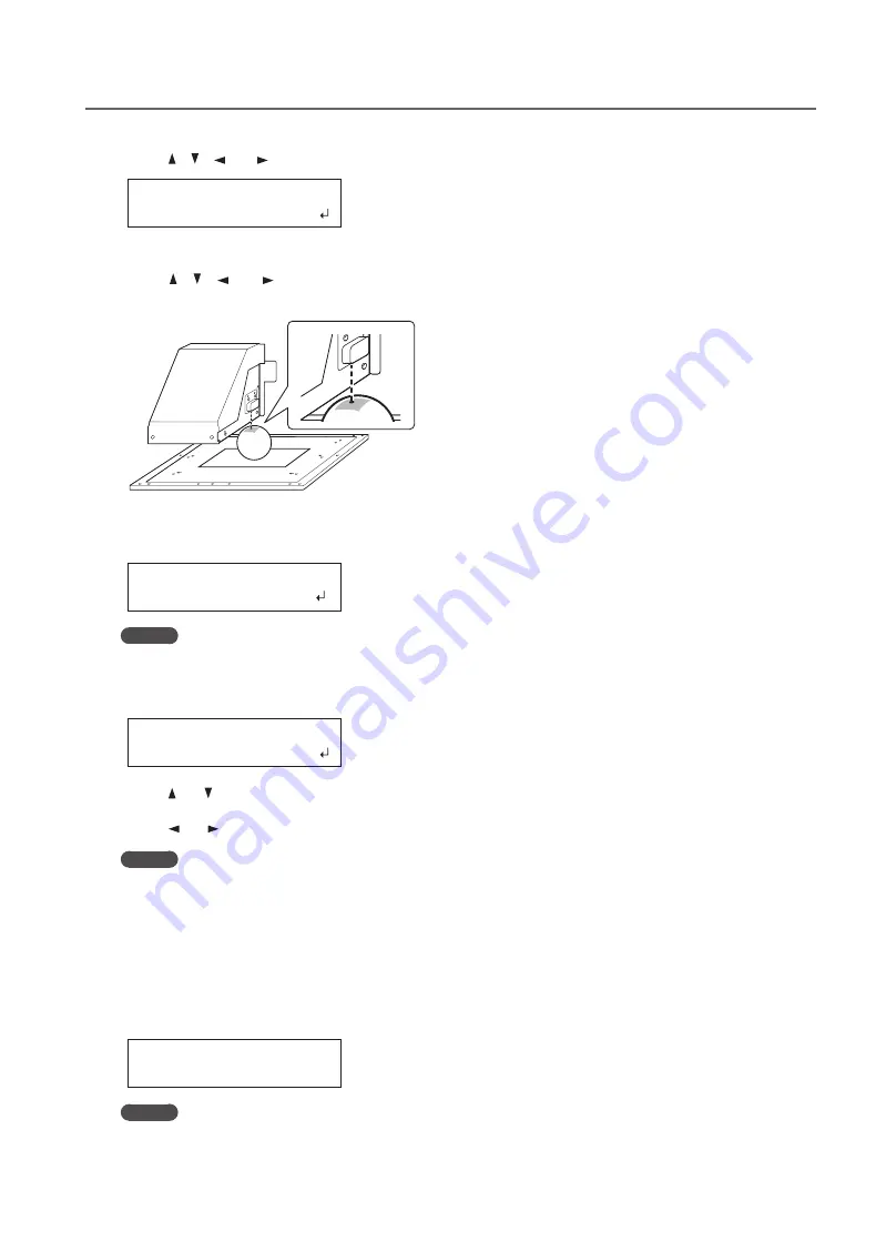
Press [ ], [ ], [ ], or [ ] when the following screen appears .

SCAN:  000.0mm
FEED:  000.0mm

The flat table moves to the rear, the print heads move to above the flat table, and the laser pointer turns on .

5. 

Press [ ], [ ], [ ], or [ ] to move the laser pointer until it points to the center position of the area you 
want to print .

6. 

Press [ENTER] .

The print heads return to the home position .

WIDTH: 000.0mm
LENGTH:000.0mm

MEMO

When the media comes into contact with the head gap sensor, the screen shown in the figure appears and 
the setup is canceled . Perform operations again from "2 . Setting the Height of the Media Automatically" 
(First Step Guide) or "Setting the Height of the Media Manually" (P . 8) .

CHECK TABLE
        HEIGHT

7. 

Press [ ] or [ ] to enter the length of the area you want to print .

8. 

Press [ ] or [ ] to enter the width of the area you want to print .

MEMO

For a test print, set "WIDTH" to 80 mm (3 .2 in .) or more and "LENGTH" to 70 mm (2 .8 in .) or more . An error 
will occur and test prints cannot be performed if the area is smaller than this .

9. 

If the front cover is open, close it .

10. 

Press [ENTER] .

The print area is specified . The print heads return to the home position .
Make sure the "W" (width), "L" (length), and "H" (height) values on the menu screen are as intended .

W:508mm L:330mm
H:100.0mm

MEMO

If you want to use the print area specified here for the next printing operation, switch "SET AT SETUP" (P . 
11) 
to "DISABLE ." With this setting, you can set up the media without setting the print area and base 
position .

Summary of Contents for VersaUV LEF-20

Page 1: ...he contents of this manual are subject to change without notice The manual and the product have been prepared and tested as much as possible If you find any misprints or errors please inform us Roland...

Page 2: ...website URL http www rolanddg com gpl Roland DG Corp has licensed the MMP technology from the TPL Group This system including the housing and safety device is a Class 1 laser product Complies with IEC...

Page 3: ...ng Print Data 21 Reducing Output Time 22 Configuring the Machine s Settings 23 Setting the Menu Language and the Units of Measurement 23 Setting the Activation Interval for Sleep Mode Power saving Fea...

Page 4: ...60 The Print Heads Do Not Move 62 Handling Messages and Error Messages 63 A Message Appears 63 An Error Message Appears 65 Main Specifications 67 Dimensional Drawings 67 Locations of the Power Rating...

Page 5: ...t Quality 17 Preventing Soiling and Dot Drop Out by Cleaning during Printing 17 Reducing Print Quality Degradation from Ink Mist Ink Spatter 18 Re Curing Ink 19 Fully Utilizing Convenient Functions 20...

Page 6: ...ject that easily reflects light as the object to be printed on the media Materials that are likely to reflect the UV LED lamp light such as mirrors and stainless steel promote the curing of the surfac...

Page 7: ...2 Setting the Height of the Media Automatically First Step Guide Setting the Height of the Media Manually P 8 Height Settings When the Print Surface is Uneven P 9 When a jig is required The object to...

Page 8: ...these presets may aid recognition Procedure 1 Set up the media height position print area and then check that SETUP is lit 2 Press MENU 3 Press then PRESET SAVE 4 Press 5 Press or to select one optio...

Page 9: ...gs are displayed HEIGHT 000 0mm 7 Press ENTER W 508mm L 330mm H 100 0mm MEMO Every time you set up the media you can set the print area base position and range For details refer to Setting the Print A...

Page 10: ...n the Print Surface is Uneven P 9 NOTE Be sure to hold the handle of the front cover and open and close it gently Procedure 1 Secure the media in place on the flat table 1 Loading Media Media Setup Fi...

Page 11: ...n is set press ENTER Height Settings When the Print Surface is Uneven This machine can also print on uneven surfaces However note the following points regarding the height setting The gap between the...

Page 12: ...ality may be deteriorated and the nozzles of the print heads may be clogged Configure the settings so that the distance between the highest position of the media and the lowest position of the print s...

Page 13: ...ice SET AT SETUP ENABLE DISABLE 4 Press or to select a value SET AT SETUP Explanation DISABLE default setting Setup is performed using the print area of the previous setup The factory default print ar...

Page 14: ...MENU SET BASE POS 5 Press SET BASE POS LOWER R LOWER R 6 Press or to select the base position SET BASE POS Print object LOWER R Set the base position home position at the front right of the print area...

Page 15: ...up the media STEP 2 Loading Media and Setting the Height First Step Guide 4 Press or when the following screen appears SCAN 000 0mm FEED 000 0mm The flat table moves to the rear the print heads move t...

Page 16: ...xt printing operation switch SET AT SETUP P 11 to DISABLE With this setting you can set up the media without setting the print area and base position Setting the Print Area Using the Center of the Med...

Page 17: ...tomatically First Step Guide or Setting the Height of the Media Manually P 8 CHECK TABLE HEIGHT 7 Press or to enter the length of the area you want to print 8 Press or to enter the width of the area y...

Page 18: ...nthelaserpointerisdifficult to see Depending on the material used on the media such as transparent media and high gloss media with dark color used on the print surface the laser pointer may be difficu...

Page 19: ...ting by removing the ink buildup before or during printing Procedure 1 Press MENU 2 Press to display the screen shown below MENU SUB MENU 3 Press 4 Press several times to display the screen shown belo...

Page 20: ...T CATCHER Explanation HIGH default setting Rotates the carriage fan at high speed MIDDLE Rotates the carriage fan at middle speed LOW Rotates the carriage fan at low speed OFF Stops the carriage fan 7...

Page 21: ...absorb ink like cloth This function may alleviate this symptom MEMO This function cannot be used if media setup has been canceled SETUP is off The UV LED lamp illuminates the print area configured in...

Page 22: ...to go back to the original screen Description When the height is readjusted automatically and printing continues the height setting is changed Therefore the print quality may be changed Hence proper p...

Page 23: ...ies in a row without replacing the media This function is useful when you want to overlay multiple images on a single piece of media DISABLE d e f a u l t setting Even when multiple data entries are s...

Page 24: ...eld the fastest output When this func tion is used the time needed for the ink to cure is not constant and an uneven color may result FULL default setting FULL makes the speed of media movement consta...

Page 25: ...TEMP UNIT Explanation C default setting In Celsius F In Fahrenheit 7 Press ENTER Setting the Activation Interval for SleepMode Power savingFeature This feature sets the time that must elapse with no...

Page 26: ...7 Press or to select DISABLE SETTING Explanation ENABLE default setting The sleep mode is acti vated after a certain period of time DISABLE The sleep mode is not activated 8 Press ENTER 9 Press MENU...

Page 27: ...ng is paused immedi ately when an ink cartridge becomes empty CONT A warning beep goes off when an ink cartridge becomes empty Printing continues until all the print data that this machine has receive...

Page 28: ...ODEL Model name SERIAL NO Serial number Ink Ink type FIRMWARE Firmware version Network Network settings such as the IP address MENU SYSTEM INFO SYSTEM INFO MODEL MODEL XXXXXX SYSTEM INFO SERIAL NO SER...

Page 29: ...k and Replacing Ink Cartridges 39 Checking for Remaining Ink 39 How to Replace the Ink Cartridges 40 When the White Ink Concentration Is Low 41 Restoring the White Ink Concentration 41 When Dot Drop O...

Page 30: ...ter specifying settings in the menus Alarm Function This function reminds you to switch on the sub power once a month When the machine remains unused for about a month this screen appears and a warnin...

Page 31: ...g so may cause a fire As part of daily cleaning wipe away any buildup of ink or grime that has adhered to the machine In particular the flat table is likely to have a buildup of grime Clean by wiping...

Page 32: ...d drain bottle do not store it in a location that is exposed to direct sunlight The discharged fluid may harden making the drain bottle unusable Dispose of discharged fluid properly in accordance with...

Page 33: ...bottle soiling your hands or the floor Discarding the Discharged Fluid before the Message Appears To discard the discharged fluid when EMPTY DRAIN BOTTLE has not been displayed yet follow the procedu...

Page 34: ...P O W E R F U L CL M a n u a l Cleaning Perform this cleaning every day when the machine s interior tends to be grimy due to the scattering of ink mist this problem tends to occur when printing with...

Page 35: ...5 Press or to select the group of print heads that is not to be cleaned Printing test results Dot drop out Group A Group B MEMO If the printing test results are difficult to interpret examine the resu...

Page 36: ...w appears when you select medium cleaning MEDIUM CL A 8 Press FUNCTION to go back to the original screen When powerful cleaning is not effective If problems such as dot drop out persist even after you...

Page 37: ...ing perform manual cleaning Replacing the wipers is also an effective means of improving the symptoms Replacing the Wipers P 46 Dot drop out Ink drips Dragging dirt Dust or other foreign matter adhere...

Page 38: ...cleaning liquid Never rub the nozzle surface of the heads Stroke the sponges very gently applying as little pressure as possible Never rub scrape or crush them If a warning beep sounds during cleanin...

Page 39: ...ten the cleaning stick with the cleaning liquid Be sure to use one of the included cleaning sticks 2 Clean in the sequence shown in the figure below Be especially careful to clean away any fibrous dus...

Page 40: ...rint head carriage moves to the right side of the machine After the operation of exiting from the manual cleaning mode the original screen is displayed again 4 Perform a Printing Test to Check the Res...

Page 41: ...reen shown below MENU INK REMAINING 3 Press Cartridge slot number Amount of ink remaining Much Little 1 2 3 4 5 6 indicates the amount of ink remaining The more there are the more ink there is remaini...

Page 42: ...with a stroke length of around 5 cm 2 in from each end of the ink cartridge 4 Pull out the empty ink cartridge and immediately insert the new one Insert the cartridge so that the side with the arrow f...

Page 43: ...e ink concentration MEMO This procedure requires some ink to be discharged so we do not recommend that you perform this procedure frequently Procedure 1 Press MENU 2 Press to display the screen shown...

Page 44: ...ver and open and close it gently Important notes on this procedure Alargeamountofinkwillbedischargedduringthisoperation Performthisoperationonlywheninkemission failures such as dot drop out cannot be...

Page 45: ...s into slots 5 and 6 RENEWING INK 10 When the screen shown below appears remove the SOL INK cleaning cartridges from slots 5 and 6 REMOVE CL LIQUID 123456 5 and 6 flash 11 Carry out steps 8 through 10...

Page 46: ...ful and manual cleaning Maintenance That Should Be Performed Daily P 28 Medium and Powerful Cleaning P 32 Manual Cleaning P 35 Be sure to use SOL INK cleaning cartridges Using any other cleaning cartr...

Page 47: ...ozzle surface is an extremely delicate mechanism make sure to perform the operations carefully and deliberately Note that this operation is an emergency measure Depending on how operations are perform...

Page 48: ...erations as specified by the instructions above and never touch any area not specified in the instructions Failure to observe this instruction may cause the machine to move suddenly resulting in injur...

Page 49: ...e new wipers Insert the wipers with the orientation shown in the figure 3 Attach the wipers to the hooks MEMO Replace the two wipers at the same time 3 Exit the REPLACE WIPER Mode NOTE Be sure to hold...

Page 50: ...tes after operation begins Stop work and close the front cover Press ENTER to exit the filter replacement menu After that restart operation from the first procedure CAUTION Be sure to perform operatio...

Page 51: ...er holder of the carriage mist fan Screw Filter Filter holder Before the replacement wipe away any buildup of ink around the fan module with a cloth 4 Replace the filter 5 Tighten the screw while push...

Page 52: ...idges may result in breakdown Once the preparations for moving are complete move the machine and fill it with ink with as little delay as possible Leaving the machine alone without ink may damage the...

Page 53: ...The machine is now ready to be moved 5 Move the machine as soon as possible 6 After moving the machine immediately reinstall it and fill it with ink See STEP 7 Filling with Ink for the FirstTime Firs...

Page 54: ...52...

Page 55: ...rinter Does Not Run 58 Attractive Printing Is Impossible 60 The Print Heads Do Not Move 62 Handling Messages and Error Messages 63 A Message Appears 63 An Error Message Appears 65 Main Specifications...

Page 56: ...T SETUP SET AT SETUP ENABLE DISABLE SUB MENU SET BASE POS SET BASE POS LOWER R CENTER SUB MENU AUTO DOWN AUTO DOWN 1 0mm 1 5mm SUB MENU FULL WIDTH S FULL WIDTH S FULL OFF SUB MENU CLEARANCE MODE CLEAR...

Page 57: ...MPTY DRAIN BOTTLE INK CONTROL HEAD WASH CLEANING LIQUID IS REQUIRED INK CONTROL CIRCULATE INK CIRCULATE INK CIR DISCHARGE INK CONTROL CHANGE INK SET CHANGE INKSET YES NO 1 SUB MENU MAINTENANCE MAINTEN...

Page 58: ...RE Ver X XX SYSTEM INFO NETWORK NETWORK IP ADDRESS IP ADDRESS 192 168 000 000 IP ADDRESS 192 168 000 003 NETWORK SUBNET MASK SUBNET MASK 255 255 255 000 SUBNET MASK 255 255 255 000 NETWORK GATEWAY ADD...

Page 59: ...G MEDIUM CL MEDIUM CL AB CLEANING POWERFUL CL POWERFUL CL AB FUNCTION PRINT AREA 1 PRINT AREA PREVIEW 1 FUNCTION UV SCANNING 1 1 Not displayed if the setup of media is not completed when SETUP is off...

Page 60: ...menu dis played If the top menu is not displayed printing will not start even when data is sent from the computer To go to the top menu press MENU and then press W 508mm L 330mm H 100 0mm Is PAUSE lit...

Page 61: ...t setting for the RIP PRINT MANAGEMENT SOFTWARE specifies the IP address set on the machine that the settings have no typing errors and for other such problems STEP 8 Network Settings First Step Guide...

Page 62: ...ur RIP PRINT MANAGEMENT SOFTWARE such as the color profile selection Select settings appropri ate for the media you are using Is the printer installed in a level and stable location Never install the...

Page 63: ...ty Are the operating param eters set to appropriate values Depending on the setting of the PERIODIC CL menu uneven colors may occur If the setting has been changed try restoring it to its default valu...

Page 64: ...sition the right side of the main unit the operation has ended successfully If the Print Heads Still Do Not Move Try switching off the main power then switching on the main power again followed by the...

Page 65: ...situations Insert the ink cartridge indicated by the flashing number REMOVE CARTRIDGE Remove the ink cartridge indicated by the flashing number CLOSE THE COVER DRY UP MAY DAMAGE THE HEAD The front co...

Page 66: ...Media Manu ally P 8 Changing the Print Area P 12 Continuing Printing Even If Media Comes into Contact with the Head Gap Sensor P 20 SETUP MEDIA This message appears when an attempt to per form a prin...

Page 67: ...FOR TABLE HEIGHT The media was detected in a posi tion at a height at which it hits the print heads Press any key except the sub power switch on the opera tion panel to make the message disappear If t...

Page 68: ...the ink cartridge to clear the error Use an ink cartridge of the specified type WRONG HEAD IS INSTALLED An unusable print head has been installed Turn off the sub power After switching off the power...

Page 69: ...ns 814 1 202 40 43 45 962 549 1 006 25 Unit mm Flat Table Dimensions 0 0 10 15 Inside of groove 40 110 210 289 310 410 500 528 538 10 15 Inside of groove 40 110 210 350 Inside of groove 345 360 24 M4...

Page 70: ...the Power Rating and Serial Number Label Serial number This is required when you seek maintenance servicing or support Never peel off the label Power rating Use an electrical outlet that meets the req...

Page 71: ...Power saving function Automatic sleep feature Power requirements 100 VAC 10 1 8 A 50 60 Hz P o w e r consumption Power on Approximately 149 W Sleep mode Approximately 13 W Acoustic noise level Power...

Page 72: ......

Page 73: ......

Page 74: ......

Page 75: ......

Page 76: ...R4 160926...

Reviews: