background image


282

Effects List

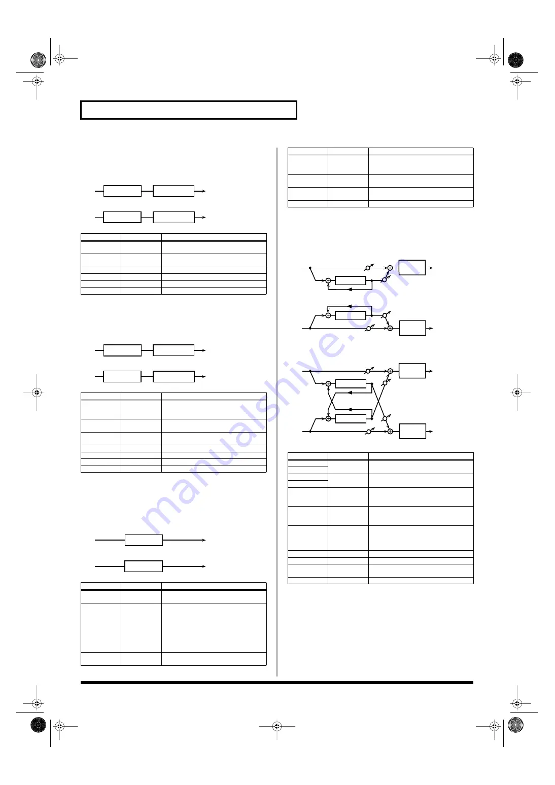
40: COMPRESSOR


Flattens out high levels and boosts low levels, smoothing out 
fluctuations in volume.


fig.MFX-40


41: LIMITER


Compresses signals that exceed a specified volume level, preventing 
distortion from occurring.


fig.MFX-41


42: GATE


Cuts the reverb’s delay according to the volume of the sound sent 
into the effect. Use this when you want to create an artificial-
sounding decrease in the reverb’s decay.


fig.MFX-42


43: DELAY


This is a stereo delay.

When Feedback Mode is NORMAL:


fig.MFX-43a


When Feedback Mode is CROSS:


fig.MFX-43b


Parameter

Value

Description


Attack #

0–127

Sets the speed at which compression 
starts

Threshold #

0–127

Adjusts the volume at which compres-
sion begins

Post Gain

0– +18 dB

Adjusts the output gain.

Low Gain

-15– +15 dB

Gain of the low frequency range

High Gain

-15– +15 dB

Gain of the high frequency range

Level #

0–127

Output level


Parameter

Value

Description


Release #

0–127

Adjusts the time after the signal volume 
falls below the Threshold Level until 
compression is no longer applied.

Threshold #

0–127

Adjusts the volume at which compres-
sion begins

Ratio

1.5:1, 2:1, 4:1, 
100:1

Compression ratio

Post Gain

0– +18 dB

Adjusts the output gain.

Low Gain

-15– +15 dB

Gain of the low frequency range

High Gain

-15– +15 dB

Gain of the high frequency range

Level #

0–127

Output level


Parameter

Value

Description


Threshold #

0–127

Volume level at which the gate begins to 
close

Mode

GATE, 
DUCK

Type of gate


GATE:


 The gate will close when the 

volume of the original sound decreas-
es, cutting the original sound.


DUCK (Ducking):


 The gate will close 

when the volume of the original 
sound increases, cutting the original 
sound.

Attack 

0–127

Adjusts the time it takes for the gate to 
fully open after being triggered.

L in

R in

L out

R out

Compressor

2-Band EQ

2-Band EQ

Compressor

L in

R in

L out

R out

Limiter

2-Band EQ

2-Band EQ

Limiter

L in

R in

L out

R out

Gate

Gate


Hold 

0–127

Adjusts the time it takes for the gate to 
start closing after the source sound falls 
beneath the Threshold.

Release

0–127

Adjusts the time it takes the gate to fully 
close after the hold time.

Balance #

D100:0W–
D0:100W

Volume balance between the direct 
sound (D) and the effect sound (W)

Level

0–127

Output level


Parameter

Value

Description


Delay Left

0–1300 ms, 
note

Adjusts the time until the delay sound is 
heard.

Delay Right
Phase Left

NORMAL, 
INVERSE

Phase of the delay sound

Phase Right
Feedback 
Mode

NORMAL, 
CROSS

Selects the way in which delay sound is 
fed back into the effect. (See the figures 
above.)

Feedback #

-98– +98 %

Adjusts the amount of the delay sound 
that’s fed back into the effect. Negative 
(-) settings invert the phase.

HF Damp

200–8000 Hz, 
BYPASS

Adjusts the frequency above which sound 
fed back to the effect is filtered out. If you 
don’t want to filter out any high frequen-
cies, set this parameter to BYPASS.

Low Gain

-15– +15 dB

Gain of the low frequency range

High Gain

-15– +15 dB

Gain of the high frequency range

Balance #

D100:0W–
D0:100W

Volume balance between the direct 
sound (D) and the delay sound (W)

Level

0–127

Output level


Parameter

Value

Description

R in

R out

L in

L out

Feedback
Feedback

Balance W

Balance D

Balance W

Balance D

2-Band

EQ

2-Band

EQ

Delay

Delay

R in

R out

L in

L out

Feedback
Feedback

Balance W

Balance D

Balance W

Balance D

2-Band

EQ

2-Band

EQ

Delay

Delay

Fantom-X678_r_e.book 282 ページ 2005年5月12日 木曜日 午後4時40分

Summary of Contents for Fantom-X6

Page 1: ...8 00 60 ROMANIA FBS LINES Piata Libertatii 1 535500 Gheorgheni ROMANIA TEL 266 364 609 RUSSIA MuTek 3 Bogatyrskaya Str 1 k l 107 564 Moscow RUSSIA TEL 095 169 5043 SPAIN Roland Iberia S L Paseo García Faria 33 35 08005 Barcelona SPAIN TEL 93 493 91 00 SWEDEN Roland Scandinavia A S SWEDISH SALES OFFICE Danvik Center 28 2 tr S 131 30 Nacka SWEDEN TEL 0 8 702 00 20 SWITZERLAND Roland Switzerland AG L...

Page 2: ...ock to persons The exclamation point within an equilateral triangle is intended to alert the user to the presence of important operating and maintenance servicing instructions in the literature accompanying the product INSTRUCTIONS PERTAINING TO A RISK OF FIRE ELECTRIC SHOCK OR INJURY TO PERSONS IMPORTANT SAFETY INSTRUCTIONS SAVE THESE INSTRUCTIONS WARNING When using electric products basic precau...

Page 3: ... any kind water soft drinks etc to penetrate the unit 012a Immediately turn the power off remove the power cord from the outlet and request servicing by your retailer the nearest Roland Service Center or an authorized Roland distributor as listed on the Information page when The power supply cord or the plug has been damaged or If smoke or unusual odor occurs Objects have fallen into or liquid has...

Page 4: ... UNIT SAFELY on pages 2 4 please read and observe the following Power Supply 301 Do not connect this unit to same electrical outlet that is being used by an electrical appliance that is controlled by an inverter such as a refrigerator washing machine microwave oven or air conditioner or that contains a motor Depending on the way in which the electrical appliance is used power supply noise may caus...

Page 5: ...r will change depending on the amount of light in the vicinity of the unit If it does not function as you expect adjust the sensitivity as appropriate for the brightness of your location Increase this value will raise the sensitivity p 226 Before Using Cards Using Memory Cards 704 Carefully insert the memory Card all the way in until it is firmly in place 705 Never touch the terminals of the memor...

Page 6: ...Structure 26 Classification of Fantom X Sound Types 26 About Simultaneous Polyphony 28 About Memory 28 Temporary Memory 29 Rewritable Memory 29 Non Rewritable Memory 29 About the Onboard Effects 29 Effect Types 29 How Effects Units Work in Different Modes 30 About the Sequencer 30 What Is a Song 30 What Is a Track 30 Songs and the Sound Generator Mode 31 Positions for Storing a Song 31 About the S...

Page 7: ...be Affected by the Controller 47 Assigning a Parameter to a Controller 48 Playing Percussion Instruments 52 Selecting a Rhythm Set 52 Playing a Rhythm Set 53 Playing in Piano Mode 54 Selecting Piano Mode 54 Selecting a Patch 54 Selecting Patches by Category 54 Selecting from the Patch List Screen 54 Playing acoustic piano sounds 54 Adjusting the Keyboard Touch Key Touch 54 Changing the Piano Sound...

Page 8: ...playing Performance Mixer Screen 97 Functions in the PERFORMANCE Layer Mixer Screen 98 Selecting a Performance 99 Selecting Performances from the List 99 Creating a list of frequently used Patches and Performances the Live Setting function 99 Selecting Favorite Performances 100 Registering a Favorite Performance 100 Using the Layer Screen 100 Selecting a Part 100 Selecting the Part that You want t...

Page 9: ...ces 128 Holding an Arpeggio 128 Playing Arpeggios Along with the Sequencer 129 Arpeggio Settings 129 Selecting Styles for Arpeggio Performances Arpeggio Style 129 Changing the Beat and Shuffle Arp Rhythm Grid 129 Applying Staccato and Tenuto Arp Rhythm Duration 130 Selecting Ascending Descending Variations Different Ways of Playing the Sounds Arp Motif 130 Adjusting the Velocity of the Arpeggio Ar...

Page 10: ...ling 144 Sampling Earlier in Time Skip Back Sampling 145 Editing a Sample 146 Selecting a Sample Sample List 146 Selecting a Sample 146 Loading a Sample 147 Loading all Samples 147 Unloading a Sample 147 Deleting a Sample 147 Importing an Audio File 148 Displaying Sample Edit Screen 148 Magnifying Shrinking the Waveform Display Zoom In Out 148 Setting the Start End Points of the Sample 149 Using t...

Page 11: ...Clear 168 Specify the Time Signature 169 Setting the tempo 169 Recording Your Performance as You Play It Realtime Recording 170 Basic Operation for Realtime Recording 170 Recording Tempo Changes in a Song Tempo Recording 171 Loop Recording and Punch In Recording 171 Correct the Timing of Your Playing as You Record Recording Quantize 172 Selecting the Sequencer Data that will Be Recorded Recording ...

Page 12: ...ading a song Save Load 198 Saving a Song Save 198 Basic Procedure 198 Data saved together with a song 198 Saving a Song with Samples Save Song Samples 199 Saving a Song Save Song 199 Saving Samples Save All Samples 200 Saving a Song as an SMF File Save as SMF 200 Loading a Song Load 201 Basic Procedure 201 Loading a Song with Samples Load Song Samples 201 Loading a song Load Song 202 Loading Sampl...

Page 13: ...Pedal D Beam 226 Keyboard 226 Sync Temp 227 Metronome 228 Sound 229 MIDI 230 USB 231 Scale Tune 232 Preview 232 System Ctrl 233 Background 233 Screen Saver 233 Sampling 233 Start up 234 System Information 234 Data Management Functions Reset to Default Factory Settings Factory Reset 235 Basic Procedure 235 Backing Up User Data User Backup 235 Restoring User Data that You Backed Up User Restore 235 ...

Page 14: ... mémoire est installée correctement 247 Using a Memory Card 248 Before Using the Memory Card 248 Writing data to the card 248 Installing the PC Card Protector 248 Troubleshooting 249 Problems Concerning the Entire Fantom X 249 Issues Related to Sound 249 Issues Related to Effects 251 Issues Related to Saving Data 251 Issues Related to Sequencer 252 Issues Related to MIDI and External Devices 253 I...

Page 15: ... simply press a single button to capture it Piano mode and Live Setting function Piano mode lets you use the Fantom X as a dedicated piano simply by pressing one button The Live Setting function provides recall of live performance setups guaranteeing smooth transitions between songs in your set A full complement of interfaces USB connector for connection to your computer USB MIDI support allows da...

Page 16: ...tion that is assigned you can use the knobs to modify the sound in realtime p 47 ASSIGNABLE switch You can assign a variety of parameters and functions to these two buttons Use them to switch the parameters and functions to modify the sound in realtime p 122 RPS Switches RPS on off p 203 Hold down SHIFT and press or rotate one of the above switches or knob to access the corresponding setting scree...

Page 17: ...s one of these buttons while holding down SHIFT the value will change in bigger increments CURSOR Moves the cursor location up down left right SHIFT JUMP This button is used in conjunction with other buttons to execute various functions ENTER Use this button to execute an operation EXIT Return to the previous screen or close the currently open window In some screens this causes the currently execu...

Page 18: ... format digital in out connectors These connectors input and output a digital audio signal stereo The output signal is identical to the signal that is output from the OUTPUT A MIX jacks S P DIF is a digital interface format used for consumer digital audio devices fig 01 007 008 OUTPUT A MIX Jacks L MONO R These jacks output the audio signal to the connected mixer amplifier system in stereo For mon...

Page 19: ... the volume and turn off the power on all devices before making any connections to Power outlet Stereo headphones Monitor speakers powered Power amp Mixer etc In order to fully experience the Fantom X s sound we recommend using a stereo amp speaker system If you re using a mono system however make your connections to the Fantom X s OUTPUT A MIX jack L MONO Audio cables are not included with the Fa...

Page 20: ...on the stand as follows fig 02 001 e Placing the Fantom X8 on a Stand For Fantom X8 user Stand screws Rubber feet of the Fantom X8 Place so that it is immediately above Center Place it so the center of the stand comes between the a and n of the word Fantom Fantom X678_r_e book 20 ページ 2005年5月12日 木曜日 午後4時40分 ...

Page 21: ...tom X fig 02 003 942 This unit is equipped with a protection circuit A brief interval a few seconds after power up is required before the unit will operate normally 3 Turn on the power for any connected amplifiers or speakers 4 Play the Fantom X s keyboard gradually increasing the setting of its volume control and then carefully raise the volume of your connected amplifiers or speakers to the desi...

Page 22: ... off the power consider these two questions Have the volume controls for the Fantom X and all connected audio devices been turned to their lowest settings Have you saved your Fantom X sounds or other data you ve created 2 Turn off the power for all connected audio devices 3 Turn off the POWER ON switch of the Fantom X Adjusting the Display Contrast LCD Contrast Turning Off the Power If you need to...

Page 23: ...lect a Demo Play and then press ENTER fig 02 007 3 Press F1 SONG1 F7 SONG7 to start demo song playback Otherwise playback will stop automatically when the song ends If you press F8 All Songs the songs will playback successively beginning from the first 4 Press F8 Exit to return to the Demo Menu screen 5 Press EXIT to return to the previous screen 982 When you play back using the procedure of steps...

Page 24: ... octave units over a range of 3 octaves by adjusting the value of the Octave Shift parameter Use KEY EFFECT OCT or OCT at the left of the screen to make the desired setting To return to the original setting press both buttons simultaneously Hold Pedal If an optional pedal switch DP series is connected to the rear panel PEDAL HOLD jack you can press the pedal switch to cause notes to sustain or hol...

Page 25: ...creen and turn the VALUE dial or press INC or DEC to change its setting fig 02 012 Roland Use only the specified expression pedal or pedal switch EV 5 DP 2 sold separately By connecting any other expression pedals you risk causing malfunction and or damage to the unit The way in which the sound changes will depend on the settings For details on settings for parameters controlled by the pedal refer...

Page 26: ...IFF format wave files as samples via a USB connection Loaded sample can be used in patches or rhythm sets When using the Fantom X you will notice that a variety of different categories come into play when working with sounds What follows is a simple explanation of each sound category Tones On the Fantom X the tones are the smallest unit of sound However it is not possible to play a tone by itself ...

Page 27: ...ts of the following four elements For details refer to the explanations for Tones WG Wave Generator 1 4 TVF Time Variant Filter TVA Time Variant Amplifier Envelope Performances A performance has a patch or rhythm set assigned to each of the 16 parts and can simultaneously handle 16 sounds The Fantom X has two screens a Layer screen and a Mixer screen p 100 p 103 Use the Layer screen if you want to...

Page 28: ...ally LAST is selected Note Priority in Performance Mode Since Performance mode is usually used to play an ensemble consisting of several patches it is important to decide which parts take priority Priority is specified by the Voice Reserve settings p 111 When a note within a patch needs to be turned off to make room for a new note the Patch Priority setting of the patch will apply p 61 Voice Reser...

Page 29: ...ctly into the temporary area and played The Fantom X has built in effect units and you can independently edit each unit s settings Multi Effects The multi effects are multi purpose effects that completely change the sound type by changing the sound itself Contained are 78 different effects types select and use the type that suits your aims In addition to effects types composed of simple effects su...

Page 30: ...cer actually plays instruments instead of the musician and since it can record a musical performance it is a tape recorder as well But in reality a sequencer doesn t record sound but actually the steps that cause the sound generator to produce sound so it offers several advantages Sound quality is always excellent the equivalent of first generation tape no matter how many times the data plays back...

Page 31: ... part playing a different sound This means that Performance mode is ideal for recording or playing an ensemble that uses multiple instruments such as drums bass and piano In Patch mode you can play using the sounds that are assigned to the Keyboard part and the Pad part Temporary Area The sequencer has an area called Temporary Area that can temporarily store one song So we call this temporary song...

Page 32: ...28 internal samples preset samples and in addition can store up to 128 user samples in a separately sold memory card fig 04 012 e Samples that you record or import are stored in sample memory This sample memory is temporary and its data will be lost when you turn off the power If you want to keep these samples you must save them to user memory or a memory card You cannot save data to the preset me...

Page 33: ...e this screen when you want to play two or more sounds patches rhythm sets together You can play patches together Layer or divide the keyboard into two regions and play different patches in each region Split MIXER display Use this screen when you want to mix the sounds by adjusting the level and pan for each of the 16 parts The Layer screen and Mixer screen provide different views of the same perf...

Page 34: ...e cursor button while you also press the cursor button for the opposite direction the cursor will move more rapidly in the direction of the first pressed cursor button When the cursor is displayed pressing ENTER will sometimes display a list of the available choices for that parameter This is convenient when you want to see what your choices are When the list is displayed you can also use the pads...

Page 35: ...n and press INC If you press INC or DEC while holding down SHIFT the value increments will get bigger Using the pads In some cases when the cursor is located at an input location you can press ENTER to see a list of parameter values For some of these lists the screen will show an icon like the following which means you can use the pads to input or specify the value When inputting a numerical value...

Page 36: ... to what it was before you changed it From MENU you can select To Upper or press to change the character at the cursor to uppercase From MENU you can select To Lower or press to change the character at the cursor to lowercase From MENU you can select Delete All to clear all the characters you were inputting Song file names may not contain lowercase characters or certain symbols Using the Pads to S...

Page 37: ...k pads the Bookmarked to that pad will appear To clear a registered page hold down CLIPBOARD in step 1 and press the pad whose registration you want to clear Here s how you can make the Fantom X s screen display a brief explanation of each button or what the button does when pressed while holding down the SHIFT key 1 Press MENU 2 Use the VALUE dial or INC DEC to select Help 3 Press ENTER The Help ...

Page 38: ...g 05 001 e 3 Press F8 Part Pad to select the Pad part fig 05 002 e 4 Press F6 to switch the Patch Play screen This screen simultaneously displays the settings of the Keyboard part and the Pad part fig 05 003_50 Press F3 Part Level to adjust the volume of the keyboard part and pad part Pressing F8 Part Level will open a window where you can adjust the volume of the keyboard part and pad part Press ...

Page 39: ...e settings of the currently selected patch and then store the modified patch in User memory and Memory card The number of onboard patches depends on the specific Wave Expansion Boards installed XP A D patches can be selected only if a Wave Expansion Board SRX series SRX series sold separately is installed in the corresponding slot 1 5 6 8 10 12 13 15 14 8 2 11 11 18 Displays the Control Setting sc...

Page 40: ... which allows you to specify a type category of patch so that you can quickly find the desired patch There are a total of 38 categories 1 Press PATCH RHYTHM to access the Patch Play screen fig 05 001 e 2 Make sure that the patch type is set to PATCH If this is set to Rhythm use CURSOR to move the cursor to the switch and turn the VALUE dial or press DEC to select Patch 3 Use CURSOR to move the cur...

Page 41: ...t ORG Organ Electric and Church Organ ACD Accordion Accordion HRM Harmonica Harmonica Blues Harp AGT AC Guitar Acoustic Guitar EGT EL Guitar Electric Guitar DGT DIST Guitar Distortion Guitar BS Bass Acoustic Electric Bass SBS Synth Bass Synth Bass STR Strings Strings ORC Orchestra Orchestra Ensemble HIT Hit Stab Orchestra Hit Hit WND Wind Winds Oboe Clarinet etc FLT Flute Flute Piccolo BRS AC Bras...

Page 42: ...anks For example you might use bank 1 to list up to sixteen sounds that you use in the first song of your live set 1 Press MENU to open the Menu window 2 Either turn the VALUE dial or press or to select Live Setting Play and then press ENTER The Live Setting Play screen appears fig 05 001b_50 You can also hold down SHIFT and press PIANO MODE to access the Live Setting Play screen 3 Press or to sel...

Page 43: ...cursor to the bank for which you want to clear the registrations 2 Hold down SHIFT and press F7 Bank Remove If you clear the entire contents of Bank 1 the display will indicate Remove Bank 1 and that bank is made empty Here s how to change the step at which a sound is registered 1 In the Live Setting Edit screen use or to move the cursor to the step at which the sound you want to move is registere...

Page 44: ...gister 1 Press PATCH RHYTHM to access the Patch Play screen to select the patch that you wish to register p 39 2 Press F2 Favorite fig 05 007_50 3 Turn the VALUE dial or press INC DEC to select the Bank 4 Hold down SHIFT and press F1 F8 to execute the registration The patch will be registered to the button you pressed 5 When you have finished registering press EXIT Using the Favorite List Screen t...

Page 45: ...er 6 Press F6 Regist to execute the registration By pressing F7 Preview you can audition the sound of the registered rhythm set Phrase Preview 7 When you have finished registering favorite patchs press EXIT to close the Favorite List screen Canceling a patch registration By pressing F4 Remove you can cancel the patch registration that is selected in the Favorite List screen The Octave Shift functi...

Page 46: ...s F7 Part Kbd or F8 Part Pad to move the cursor to the pad part or the keyboard part 3 Press F5 Tone Sw Sel fig 05 014_50 4 Press F1 Tone Sw F4 Tone Sw to turn each tone on off The setting will switch on off each time you press the button 5 Press EXIT to close the window If you want just one or two tones to sound in a patch turn the others off and store that setting on a patch This cuts nonessenti...

Page 47: ...ches you can use a button to easily turn portamento on off p 125 The Fantom X lets you assign the parameters that will be affected when you operate the realtime control knobs assignable switches D Beam pitch bend or modulation lever This lets you modify the sound in a variety of ways by operating the controllers You can specify whether operating the controller will affect the sound assigned to the...

Page 48: ...each performance as part of the performance settings This lets you create performances that make effective use of controller settings fig 05 018_50 For details on these settings refer to Assigning a Parameter to a Controller p 48 Pad Number Specifies the pad number affected by the D Beam When the cursor is located at this parameter you can also make this setting by striking the desired pad Value 0...

Page 49: ...n the OSC2 pitch Value OFF ON Filter Type Selects the type of filter OFF No filter is used LPF Low Pass Filter This reduces the volume of all frequencies above the cutoff frequency Cutoff Freq in order to round off or un brighten the sound This is the most common filter used in synthesizers BPF Band Pass Filter This leaves only the frequencies in the region of the cutoff frequency Cutoff Frequency...

Page 50: ...ter to a Controller p 48 Type Specifies the function controlled by the D Beam controller Value CC01 31 33 95 Controller numbers 1 31 33 95 For more information about Control Change messages please refer to MIDI Implementation p 298 Bend Up Raises the pitch in semitone steps up to 4 octaves higher Bend Down Lowers the pitch in semitone steps up to 4 octaves lower Start stop Starts Stops the sequenc...

Page 51: ...ls the playback position of the arpeggio pattern Digital In Input level from DIGITAL IN Switch fig 05 022_50 For details on these settings refer to Assigning a Parameter to a Controller p 34 Assignable switches are valid only when the keyboard part is selected Switch 1 2 Assignable Switch 1 2 Specify the functions that will be controlled by the buttons Value Transpose Down Lowers the key range in ...

Page 52: ...ected rhythm sets from this group cannot be changed The Fantom X includes nine preset rhythm sets XP A D Wave Expansion Boards installed in EXP A D Slots These groups are for when using rhythm sets from a Wave Expansion Board installed in slots EXP A D and cannot be rewritten However you can modify the settings of the currently selected rhythm set and then save the modified settings in User memory...

Page 53: ...lect the rhythm set that you wish to play 3 Press a key or a pad on the keyboard to play a percussion instrument Below the rhythm set name the screen shows the note name of the key you pressed and the name of the percussion instrument rhythm tone name assigned to that key fig 05 024 e Playing a Rhythm Set Note name Rhythm tone name Fantom X678_r_e book 53 ページ 2005年5月12日 木曜日 午後4時40分 ...

Page 54: ..._50 2 Press or to select the patch 3 Press F1 or F2 to select the desired category 4 Turn the VALUE dial or press INC DEC and then press F8 Select to select the patch By pressing F7 Preview you can audition a patch using a preselected phrase appropriate for that type category of patch Phrase Preview By pressing F6 System Write you can register the currently selected patch as the one that will be f...

Page 55: ...iano Value 1 6 When you hold down the damper pedal on an acoustic piano the strings notes you play will cause the other strings to resonate sympathetically creating a rich and spacious resonance You can adjust the depth of this resonance 1 From the Piano Mode screen press F4 Resonance fig 27 005_50 2 Either turn the VALUE dial or use INC DEC to set the value You can press a button F4 F8 to access ...

Page 56: ...ing them light red To switch a tone on off Press a F1 Tone Sw F4 Tone Sw button to switch the corresponding tone on off You can also select the tone by pressing or You can also hold down SHIFT and press F1 F8 to select a tone to edit or to switch a tone on off 6 When you have made your selection press EXIT 7 Turn the VALUE dial or press INC DEC to get the value you want If you ve selected two or m...

Page 57: ...rameters that you want to edit To switch the parameter you want to edit Press F6 To switch to a different part for editing Press F7 Part Select To select a tone for editing or switch a tone on off Press F8 Tone Sw Sel 4 Use CURSOR to move the cursor to the parameter that you want to edit You can use the realtime control knob to set the value 5 Turn the VALUE dial or use INC DEC to modify the value...

Page 58: ... that are elements of other sounds These include attack components such as piano hammer sounds and guitar fret noises Looped These waveforms include sounds with long decays as well as sustained sounds Loop waveforms repeatedly play back loop the portion of the waveform after the sound has reached a relatively steady state The Fantom X s looped waveforms also include components of other sounds such...

Page 59: ...ant to keep the modified sound you must save it in the internal USER group user memory When you edit the patch settings an will appear in the Patch Play screen When you perform the save procedure the data that previously occupied the save destination will be lost 1 Make sure that the patch you wish to save is selected 2 Press WRITE The Write Menu screen appears fig 06 007_50 3 Press F2 Patch Rhyth...

Page 60: ...ssage will ask you for confirmation 6 Press F8 Exec once again to execute the Save operation This section explains the functions the different patch parameters have as well as the composition of these parameters Parameters marked with a can be controlled using specified MIDI messages Matrix Control Settings in the Control screen will determine how these parameters are controlled p 80 If a number i...

Page 61: ... acoustic pianos are normally tuned causing the lower range to be lower and the higher range to be higher than the mathematical tuning ratios would otherwise dictate With a setting of OFF the patch s tuning will be equal temperament A setting of 3 will produce the greatest difference in the pitch of the low and high ranges Value OFF 1 3 The diagram shows the pitch change relative to equal temperam...

Page 62: ...ity Sens Offset Velocity Sensitivity Offset Velocity Sensitivity Offset alters the Velocity Sensitivity of the overall patch while preserving the relative differences between the Velocity Sensitivity values set for each tone in the parameters below Cutoff V Sens parameter p 70 Level V Sens parameter p 71 Range 63 63 Velocity Pressure with which the key is pressed This value is added to the velocit...

Page 63: ...ith which keys are played or MIDI messages to control the way each Tone is played This is referred to as the Tone Mix Table TMT fig 06 013_50 For details on these settings refer to How to Make Patch Settings p 56 Structure Type 1 2 3 4 Determines how tone 1 and 2 or tone 3 and 4 are connected Value 1 10 The following 10 different Types of combination are available fig 06 014 With this type tones 1...

Page 64: ...lume balance of the two tones adjusting the depth of ring modulator fig 06 023 This type passes the filtered sound of each tone through a ring modulator to create new overtones and also mixes in the sound of tone 2 4 Since the ring modulated sound can be mixed with tone 2 4 tone 1 3 TVA can adjust the amount of the ring modulated sound When TYPE 2 10 is selected and one tone of a pair is turned of...

Page 65: ...o lower the upper key below the lower key the other value will be automatically modified to the same setting Booster The Booster is used to distort the incoming signal fig 06 024 e In addition to using this to create distortion you can use the waveform WG1 of one of the tones as an LFO which shifts the other waveform WG2 upward or downward to create modulation similar to PWM pulse width modulation...

Page 66: ...s the lowest velocity at which the tone will sound Make these settings when you want different tones to sound in response to notes played at different strengths Value 1 UPPER Velo Range Upper Velocity Range Upper This sets the highest velocity at which the tone will sound Make these settings when you want different tones to sound in response to notes played at different strengths Value LOWER 127 I...

Page 67: ...00 110 120 130 140 150 160 170 180 190 200 fig 06 030 e Bend Range Up Pitch Bend Range Up Specifies the degree of pitch change in semitones when the Pitch Bend lever is all the way right For example if this parameter is set to 12 the pitch will rise one octave when the pitch bend lever is moved to the right most position Value 0 48 Bend Range Down Pitch Bend Range Down Specifies the degree of pitc...

Page 68: ... Pitch Env P Env Depth Pitch Envelope Depth Adjusts the effect of the Pitch Envelope Higher settings will cause the pitch envelope to produce greater change Negative settings will invert the shape of the envelope Value 12 12 P Env Time 1 4 Pitch Envelope Time 1 4 Specify the pitch envelope times Time 1 Time 4 Higher settings will result in a longer time until the next pitch is reached For example ...

Page 69: ... Cutoff frequency While this filter is also good for use with simulated acoustic instrument sounds the nuance it exhibits differs from that of the LPF2 even with the same TVF Envelope settings If you set LPF2 or LPF3 the setting for the Resonance parameter will be ignored p 69 Cutoff Frequency Selects the frequency at which the filter begins to have an effect on the waveform s frequency components...

Page 70: ...nce V Sens Resonance Velocity Sensitivity This allows keyboard velocity to modify the amount of Resonance If you want strongly played notes to have a greater Resonance effect set this parameter to positive settings If you want strongly played notes to have less Resonance use negative settings Value 63 63 F Env V Curve TVF Envelope Velocity Curve Selects one of the following 7 curves that will dete...

Page 71: ...ff frequency value specified in the TVF screen Value 0 127 fig 06 038_50 For details on these settings refer to How to Make Patch Settings p 56 TVA Tone Level Sets the volume of the tone This setting is useful primarily for adjusting the volume balance between tones Value 0 127 Level V Curve TVA Level Velocity Curve You can select from seven curves that determine how keyboard playing strength will...

Page 72: ...produce greater change Value 100 100 fig 06 040 e Random Pan Depth Use this parameter when you want the stereo location to change randomly each time you press a key Higher settings will produce a greater amount of change Value 0 63 Alter Pan Depth Alternate Pan Depth This setting causes panning to be alternated between left and right each time a key is pressed Higher settings will produce a greate...

Page 73: ...no plug is actually inserted in the INDIVIDUAL 2 jack the sounds routed to INDIVIDUAL 1 and INDIVIDUAL 2 will be mixed and output from the INDIVIDUAL 1 jack If the Mix Parallel parameter MENU System General is set to MIX all sounds are output from the OUTPUT A MIX jacks in stereo p 230 Tone Out Assign Specifies how the direct sound of each tone will be output Value MFX Output in stereo through mul...

Page 74: ... Sine wave TRI Triangle wave SAW U Sawtooth wave SAW D Sawtooth wave negative polarity SQR Square wave RND Random wave BND U Once the attack of the waveform output by the LFO is allowed to develop in standard fashion the waveform then continues without further change BND D Once the decay of the waveform output by the LFO is allowed to develop in standard fashion the waveform then continues without...

Page 75: ... Follow Adjusts the value for the Delay Time parameter depending on the key position relative to the C4 key center C To decrease the time that elapses before the LFO effect is applied the effect is continuous with each higher key that is pressed in the upper registers select a positive value to increase the elapsed time select a negative value Larger settings will produce greater change If you do ...

Page 76: ...FO gradually after the key is pressed fig 06 043 e Fade Mode ON Delay Time The time from when the keyboard is played until the LFO begins to be applied Fade Time The time over which the LFO amplitude will reach the maximum after the Delay Time has elapsed Apply the LFO immediately when the key is pressed and then gradually begin to decrease the effect fig 06 044 e Fade Mode ON Delay Time The time ...

Page 77: ...rases or when using modulation with the mono synth keyboard sound Value OFF ON Portamento Switch Specifies whether the portamento effect will be applied ON or not OFF Value OFF ON Portamento Mode Specifies the performance conditions for which portamento will be applied Value NORMAL Portamento will always be applied LEGATO Portamento will be applied only when you play legato i e when you press the ...

Page 78: ... change to the next note to take more time Value 0 127 fig 06 050_50 Tone Delay Mode Selects the type of tone delay Value NORM The tone begins to play after the time specified in the Delay Time parameter has elapsed fig 06 051 e HOLD Although the tone begins to play after the time specified in the Delay Time parameter has elapsed if the key is released before the time specified in the Delay Time p...

Page 79: ...US Range NO SUS SUST If a one shot type Wave p 58 is selected it will not sustain even if this parameter is set to SUST Tone Rx Bender Tone Receive Pitch Bend Switch For each tone specify whether MIDI Pitch Bend messages will be received ON or not OFF Value OFF ON Tone Rx Expression Tone Receive Expression Switch For each tone specify whether MIDI Expression messages will be received ON or not OFF...

Page 80: ...ted to change tone parameters using an external MIDI device you would need to send System Exclusive messages MIDI messages designed exclusively for the Fantom X However System Exclusive messages tend to be complicated and the amount of data that needs to be transmitted can get quite large For that reason a number of the more typical of the Fantom X s tone parameters have been designed so they acce...

Page 81: ...trix Control will be received If the Fantom X is set up such that reception of MIDI messages is disabled then the Matrix Control will not function CTRL Destination 1 4 Matrix Control Destination 1 4 Matrix Control Destination selects the tone parameter that is to be controlled when using the Matrix Control The following parameters can be controlled When not controlling parameters with the Matrix C...

Page 82: ...ied by MFX Control 1 4 Assign parameter If you have not made the necessary settings for using the multi effect the multi effect will not be applied even if you attempt to control it as a Matrix Control destination If you re not using Matrix Control OFF Matrix Control will not be used CTRL Sens 1 4 Matrix Control Sens 1 4 Sets the amount of the Matrix Control s effect that is applied If you wish to...

Page 83: ...o edit For details on how the parameters are grouped refer to Rhythm Set Parameter p 259 4 Use or to move the cursor to the parameter you wish to modify 5 Press F8 Wave Sw Sel to select the wave that you want to edit The Wave Sw Select window will appears fig 05 011_50 Press any one of the F5 Wave Select1 F8 Wave Select4 buttons to select the wave that you want to edit Simultaneously editing the s...

Page 84: ...t you want to initialize p 52 2 Hold down SHIFT and press F1 Init A message will ask you for confirmation 3 Press F8 Exec The initialization will be carried out and you ll be returned to the previous screen To cancel press F7 Cancel Initializing only a specific key Here s how to initialize only a specific key of a Rhythm Set 1 Press PATCH RHYTHM to access the Patch Play screen and select the part ...

Page 85: ...eforms also include components of other sounds such as piano string resonant vibrations and the hollow sounds of brass instruments Cautions When Using a One shot Waveform It is not possible to use the envelope to modify a one shot waveform to create a decay that is longer than the original waveform or to turn it into a sustaining sound If you were to program such an envelope you would be attemptin...

Page 86: ... memory card Card fig 07 007_50 By pressing F6 Compare you can check the save destination Rhythm set Compare function 7 Press F8 Write A message will ask you for confirmation Never switch off the Fantom X while data is being saved 8 Press F8 Exec to execute the save operation To cancel the operation press F7 Cancel To cancel press F7 Cancel Before you save a rhythm set you can audition the rhythm ...

Page 87: ...e Wave Level parameter p 90 Tone Name Rhythm Tone Name You can assign a name of up to 12 characters to the rhythm tone Value space A Z a z 0 9 _ For details on assigning names refer to Assigning a Name p 36 Assign Type Assign Type sets the way sounds are played when the same key is pressed a number of times Value MULTI Layer the sound of the same keys Even with continuous sounds where the sound pl...

Page 88: ... result will be the same as when the envelope s Tone Env Mode parameter p 87 is set to NO SUS If you have set Wave Group p 88 to Sample the loop setting will be forced to ONE SHOT Value OFF ON Aftertouch Time Ctrl Sens Sensitivity If Wave Group is set to SAMPLE and Tempo Sync is ON aftertouch will control the amount of time stretching shrinking caused by Time Stretch If Time Stretch is not being a...

Page 89: ...ill be used ON or not OFF Value OFF ON FXM Color Specifies how FXM will perform frequency modulation Higher settings result in a grainier sound while lower settings result in a more metallic sound Value 1 4 FXM Depth Specifies the depth of the modulation produced by FXM Value 0 16 When the Tempo Sync parameter is set to ON settings related to Pitch p 91 and FXM p 89 are disabled The WMT Wave Mix T...

Page 90: ...do not want the panning to change each time a key is pressed set this to OFF Range OFF ON REV Velo Fade Lower Velocity Fade Width Lower This determines what will happen to the tone s level when the tone is played at a velocity lower than its specified velocity range Higher settings produce a more gradual change in volume If you want notes played outside the specified key velocity range to not be s...

Page 91: ...tch envelope to have less effect for strongly played notes set this to a negative value Value 63 63 P Env T1 V Sens Pitch Envelope Time 1 Velocity Sensitivity This allows keyboard dynamics to affect the Time 1 of the Pitch envelope If you want Time 1 to be speeded up for strongly played notes set this parameter to a positive value If you want it to be slowed down set this to a negative value Value...

Page 92: ...according to the Cutoff frequency While this filter is also good for use with simulated acoustic instrument sounds the nuance it exhibits differs from that of the LPF2 even with the same TVF Envelope settings If you set LPF2 or LPF3 the setting for the Resonance parameter will be ignored Cutoff Frequency Selects the frequency at which the filter begins to have an effect on the waveform s frequency...

Page 93: ...VF envelope Positive settings will cause the TVF envelope to have a greater effect for strongly played notes and negative settings will cause the effect to be less Value 63 63 F Env T1 V Sens TVF Envelope Time 1 Velocity Sensitivity This allows keyboard dynamics to affect the Time 1 of the TVF envelope If you want Time 1 to be speeded up for strongly played notes set this parameter to a positive v...

Page 94: ...unt of change Value 0 63 This will affect only waves whose Wave Rnd Pan Sw parameter p 90 is ON Alternate Pan Depth This setting causes panning to be alternated between left and right each time a key is pressed Higher settings will produce a greater amount of change L or R settings will reverse the order in which the pan will alternate between left and right For example if two rhythm tones are set...

Page 95: ...assing through multi effects 1 4 Output to the INDIVIDUAL 1 4 jacks in mono without passing through multi effects If the Rhythm Output Assign is set to anything other than TONE these settings will be ignored If you ve made settings so that sounds are separately routed to the INDIVIDUAL 1 jack and INDIVIDUAL 2 jack but no plug is actually inserted in the INDIVIDUAL 2 jack the sounds routed to INDIV...

Page 96: ... the signal sent to reverb for each tone if the tone is not sent through MFX Value 0 127 For details regarding effect settings refer to the pages shown below Applying Effects in Patch Mode p 207 Making Multi Effects Settings MFX1 3 p 213 Making Chorus Settings Chorus p 215 Making Reverb Settings Reverb p 216 3 4 Setting Effects for a Rhythm Set Effects MFX MFX Control Chorus Reverb Fantom X678_r_e...

Page 97: ...he current part and the parts whose keyboard switch has a check mark In addition to the settings of each part the following settings can also be stored for each performance Controller settings such as the D Beam realtime control knobs assignable switches and pads Arpeggio and chord memory settings Rhythm group number To access the Performance Layer screen use the following procedure 1 Press PERFOR...

Page 98: ...1 9 Set the volume LEVEL pan PAN reverb REV chorus CHO Mute Sw M Solo Sw S of the part The setting screen is divided into two screens and you can press function button F6 to switch between them Set the Part Course Tune Key Output Assign Keyboard Sw K reverb REV Arpeggio Part A Pad Part P of the part The setting screen is divided into two screens and you can press function button F6 to switch betwe...

Page 99: ... group fig 08 003 e 3 Turn the VALUE dial or press INC DEC to select a performance group USER User PRST Preset CARD Memory Card 4 Press CURSOR to move the cursor to the performance number 5 Turn the VALUE dial or press INC DEC to select the performance number You can display a list of performances and select a performance from that list 1 Press LAYER SPLIT or MIXER 2 Press F5 Perf List The Perform...

Page 100: ...Wave Expansion Board You can register a total of 64 Performances 8 sounds x 8 banks as favorite Performance For details on selecting a favorite performance refer to Selecting Favorite Performances p 100 1 Select the Performance that you wish to register p 99 2 Press F5 Perf List 3 Press F3 Favorite The Favorite List screen appears fig 08 006_50 4 Press F1 F2 to select the bank in which you wish to...

Page 101: ... List screen will appear fig 05 008_50 To cancel press EXIT 3 Use or to select a patch If you press F4 Patch Categ the list will show the categories If you press F5 Patch or F6 Rhythm the list will show the patch groups fig 05 009_50 To switch groups press F1 F2 By pressing F7 Preview you can audition a patch using a preselected phrase appropriate for that type category of patch Phrase Preview 4 P...

Page 102: ...ER SPLIT to access the Layer screen 2 Press or to select the part you want to play 3 Press F3 Key Range 4 Press F3 KBD move the cursor to the keyboard switch and press INC to turn on the keyboard switch that is connected to the part you want to sound 5 To set the lower limit of the range use F4 Lower to move the cursor to Key Range Lower To set the lower limit of the range use F5 Upper to move the...

Page 103: ...tch 2 Press F1 Patch List The Patch List screen will appear fig 05 008_50 To cancel press EXIT 3 Use or to select a patch If you press F4 Patch Categ the list will show the categories If you press F5 Patch or F6 Rhythm the list will show the patch groups fig 05 009_50 To switch groups press F1 F2 By pressing F7 Preview you can audition a patch using a preselected phrase appropriate for that type c...

Page 104: ...nce Mixer 1 screen will appear If you want to edit the parameters of the Performance Mixer 2 screen press F6 to switch screens fig 04 016_50 2 Use or to move the cursor to the parameter you want to edit 3 Use or to move the cursor to the part that you want to edit 4 Turn the VALUE dial or use INC DEC to set the desired value The green border enclosing four parts corresponds to the four REALTIME CO...

Page 105: ... 08 016a_50 Part Mute does not turn off the MIDI receive switch rather it sets the volume to the minimum setting to silence the sound Therefore MIDI messages are still received Part Mute does not turn off the MIDI receive switch rather it sets the volume to the minimum setting to silence the sound Therefore MIDI messages are still received You can use the pads to switch part muting on off Pad numb...

Page 106: ...wed for each part This is useful when you want to check whether the sound generator is responding correctly to the keyboard or to operations from an external MIDI controller 1 Access the Performance Layer or Mixer screen p 97 2 Hold down SHIFT and press F2 Part Info The Part Information window appears fig 08 018_50 3 Turn VALUE dial or press INC DEC to select the message that you want to check Mod...

Page 107: ...OR to move the cursor to the parameter you want to change 4 Turn the VALUE dial or press INC DEC set the value The name of the parameter at the cursor location is displayed in the bottom line of the Part View screen F1 Level Pan Patch Type Sets the assignment of a patch Patch or rhythm set Rhythm to each of the parts Patch Bank Selects the group to which the desired patch or rhythm set belongs Val...

Page 108: ...ereo p 230 If you ve set Tone Out Assign to MFX set the MFX Output Assign parameter to specify the output destination of the sound that has passed through the multi effects Chorus and reverb are output in mono at all times The output destination of the signal after passing through the chorus is set with the Chorus Output Select p 209 and the Chorus Output Assign p 209 The output destination of the...

Page 109: ...cur when the Pitch Bend Lever is moved The amount of change when the lever is tilted is set to the same value for both left and right sides If you want to use the Pitch Bend Range setting of the patch assigned to the part p 67 set this to PAT Value 0 24 PAT Part Portamento Switch Specify whether portamento will be applied Turn this parameter ON when you want to apply Portamento and OFF when you do...

Page 110: ...tone s Time 1 parameter is already set to 127 maximum there will be no change produced by setting the Attack Time Offset to a positive value The same applies to the TVF envelope Part Release Time Offset Adjusts the TVA TVF Envelope Release Time for the patch or rhythm set assigned to a part Value 64 63 Patches also contain a Release Time Offset setting p 62 The final TVA Envelope release time valu...

Page 111: ...brato Depth For each part this adjusts the depth of the vibrato effect the depth at which the pitch is modulated The pitch will be modulated more greatly for higher settings and less with lower settings Value 64 63 Part Vibrato Delay For each part this adjusts the time delay until the vibrato pitch modulation effect begins Higher settings will produce a longer delay time before vibrato begins whil...

Page 112: ... you want to transmit 0 128 for each part If you do not want this message to be transmitted set this to OFF Value 1 128 OFF The data of the part for which the Keyboard Switch is turned off will not be transmitted Ext Level External Level If you want Volume messages to also be transmitted when you select a Performance specify the desired value 0 127 for the part If you do not want this message to b...

Page 113: ...odulation Receive Modulation Switch For each MIDI channel specify whether MIDI Modulation messages will be received ON or not OFF Assigning a check mark will enable reception and removing the check mark will disable reception Volume Receive Volume Switch For each MIDI channel specify whether MIDI Volume messages will be received ON or not OFF Assigning a check mark will enable reception and removi...

Page 114: ...to the Performance Layer or Mixer screen If you return to the Performance PLAY screen without saving the display will indicate reminding you that the Performance settings have been modified If you turn off the power or select a different sound while the display indicates your edited Performance will be lost fig 09 013_50 For details on these settings refer to Selecting the Parameter Controlled by ...

Page 115: ...ve when the OSC1 pitch is higher than the OSC2 pitch Value OFF ON Filter Type Selects the type of filter OFF No filter is used LPF Low Pass Filter This reduces the volume of all frequencies above the cutoff frequency Cutoff Freq in order to round off or un brighten the sound This is the most common filter used in synthesizers BPF Band Pass Filter This leaves only the frequencies in the region of t...

Page 116: ...This lets you create performances that make effective use of controller settings Type Assignable Type Specifies the function controlled by the D Beam controller Value CC01 31 33 95 Controller numbers 1 31 33 95 For more information about Control Change messages please refer to MIDI Implementation p 298 Bend Up Controls the pitch as specified by the Pitch Bend Range Up setting p 67 Bend Down Contro...

Page 117: ...e DIGITAL OUT jack The panel VOLUME knob only adjusts the volume of the OUTPUT A jacks Arp Step Controls the playback position of the arpeggio pattern Digital In Input level from DIGITAL IN Switch fig 09 017_50 For details on these settings refer to Selecting the Parameter Controlled by the Realtime Controllers or D Beam Controller Control Setting p 114 Switch 1 2 Assignable Switch 1 2 Specify the...

Page 118: ... used Value 1 16 OFF You can change controller switch on off settings for each patch in the performance 1 In the Control Setting Performance screen press F7 Ctrl Switch fig 09 012_50 2 Use CURSOR to move the cursor to the parameter you wish to modify 3 Turn the VALUE dial or press INC DEC to get the value you want 4 Repeat steps 2 3 to set each parameter you want to edit 5 Press F8 EXIT to return ...

Page 119: ...d to a standard set of values The Initialize operation will affect only the currently selected sound the sounds that are stored in user memory will not be affected If you wish to restore all of the Fantom X s settings to their factory values perform a Factory Reset p 235 1 Select the Performance that you wish to initialize p 99 2 Hold down SHIFT and press F1 Init The Performance Initialize window ...

Page 120: ... Name p 36 5 When you have finished inputting the name press F8 Write A screen will appear allowing you to select the write destination performance fig 09 023_50 6 Press F1 or F2 to select the write destination Then the VALUE dial or use INC DEC to select the performance number The write destination can be either the Fantom X s internal user area User or a memory card Card 7 Press F8 Write A messa...

Page 121: ...hile you play the keyboard or pads to produce sound place your hand above the D Beam controller and move it slowly up and down An effect will be applied to the sound depending on the function that is assigned to the D Beam controller 4 To turn off the D Beam controller once again press the button you pressed in step 2 so the indicator goes out If Performance mode is selected the D Beam controller ...

Page 122: ...octaves Arp Step Controls the playback position of the arpeggio pattern Aftertouch Aftertouch Range Min D Beam Range Lower Specify the lower limit of the range of the D Beam controller Value 0 127 Range Max D Beam Range Upper Specify the upper limit of the range of the D Beam controller By setting Range Max below Range Min you can invert the range of change Value 0 127 The settings for the ASSIGNA...

Page 123: ...settings OSC 1 2 Waveform Select the waveform SAW is a sawtooth wave and SQR is a square wave Value SAW SQR OSC 1 2 Pulse Width Specifies the pulse width of the waveform By cyclically modifying the pulse width you can create subtle changes in the tone The Pulse Width is activated when SQR is selected with OSC1 2 waveform Value 0 127 OSC 1 2 Coarse Tune Adjusts the pitch of the tone s sound up or d...

Page 124: ...s and ASSIGNABLE SW buttons to modify the sound in real time 1 Access the Patch Play screen p 38 The Realtime Control area shows the function that is assigned to each realtime controller knob and button indicate the four knobs and indicate the two buttons fig 10 007 e 2 You can select the function of the knobs by pressing the button located at the right of the realtime control knobs The parameter ...

Page 125: ...ntrols the playback position of the arpeggio pattern DIGITAL IN Input level from DIGITAL IN Assignable Switch Settings 1 Hold down SHIFT and press one of the ASSIGNABLE SW button The Switch screen appears fig 10 009_50 2 Move the cursor to the parameter that you want to set and turn the VALUE dial or press INC DEC to make the setting 3 If you want to save your settings press F8 System Write Press ...

Page 126: ...al PROG UP The next sound number will be selected PROG DOWN The previous sound number will be selected FAVORITE UP The favorite patch performance of the next number or bank will be selected FAVORITE DOWN The favorite patch performance of the previous number or bank will be selected ARP SW Switches the Arpeggio Rhythm function on off RHY START STOP Switch Rhythm pattern playback on off CHORD SW Swi...

Page 127: ...127 Modifying the Sound in Real Time Fantom X678_r_e book 127 ページ 2005年5月12日 木曜日 午後4時40分 ...

Page 128: ...urrent tempo value appears in the display fig 11 002_50 2 Press VALUE dial or INC DEC to set the tempo value 5 300 or set the value by tapping F6 Tap a number of times with the same rhythm Tap Tempo If you press F7 Click to light it in red the click will sound 3 When you have made the setting press F8 Close By using the following procedure you can produce arpeggios even without continuing to press...

Page 129: ...one beat 1 8 Eighth note two grid sections one beat 1 8L Eighth note shuffle Light two grid sections one beat with a light shuffle 1 8H Eighth note shuffle Heavy two grid sections one beat with a heavy shuffle 1 12 Eighth note triplet three grid sections one beat 1 16 Sixteenth note four grid sections one beat 1 16L Sixteenth note shuffle Light four grid sections one beat with a light shuffle 1 16...

Page 130: ...se order No note is played every time RANDOM L Notes will be sounded randomly for the keys you press with only the lowest key sounded each time RANDOM _ Only the lowest of the keys pressed is sounded each time the notes you press will be sounded randomly No note will sound each time PHRASE Pressing just one key will play a phrase based on the pitch of that key If you press more than one key the ke...

Page 131: ...ed to initialize the Style In the Arpeggio Style Edit screen hold down SHIFT and press F1 Init A message will ask whether you want to initialize press F8 Exec to execute initialization 1 Hold down SHIFT and press ARPEGGIO 2 Press F7 Edit The Arpeggio Style Edit screen will appear 3 Press F1 Arp Setup The Arpeggio Setup screen will appear 4 Move the cursor to End Step and specify the number of step...

Page 132: ...ter you ve specified the step and pitch to be input strike a pad to input it Higher numbered pads produce higher velocity values for example striking pad 1 specifies a velocity value of 8 while striking pad 16 specifies a velocity value of 127 A maximum of sixteen note numbers pitches can be used in a single style The Styles you create are temporary they are deleted as soon as you turn off the pow...

Page 133: ...e chord is played using the exact chord structure recorded in the Chord Form This is referenced to the C4 key parallel chords are played by pressing other keys 3 To finish playing arpeggios press CHORD MEMORY again to turn it off Changing the chord form will change the notes in the chord 1 Hold down SHIFT and press CHORD MEMORY The following screen appears If Performance mode is selected Performan...

Page 134: ...ay When you press a key the note will be added in the screen If you input a note by mistake press F5 Del Note You can also erase a note you input by pressing the same key You can press F6 Preview to hear the chord that you are inputting 5 If you want to save the chord form you created proceed to step 3 of Saving the Chord Forms You Have Created If you don t want to save it press F7 Exit The Chord ...

Page 135: ...to turn it on The button will light fig 11 001 2 Play a pad 9 16 According to the pad you pressed the assigned rhythm pattern will begin playing The volume of the rhythm pattern will also change according to how strongly you strike the pad fig 13 001 e A pattern will begin playing when you press any pad from 9 16 that isn t illuminated A rhythm tone will sound when you press a pad that is blink Th...

Page 136: ... the right of Rhythm Pattern fig 13 003_50 3 Press or to move the cursor to each parameter and either turn the VALUE dial or press INC or DEC to make the setting You can audition the rhythm pattern by pressing F6 Preview so it lights in red When you ve finished auditioning the pattern press F6 Preview once again to stop 4 When you have made the setting press EXIT Select the basic playing style of ...

Page 137: ...he next new sound is specified This has no effect if the Tone Env Mode parameter p 87 is set to No Sus This specifies the strength with which the Pads you press will be sounded If you want the velocity to change according to the force with which you press the Pads set this to REAL If you want the velocity to be a fixed value regardless of the force with which you press the Pads specify the desired...

Page 138: ...n use F4 Zoom In F5 Zoom Out to zoom the display in or out You can press F6 Preview to audition the style you ve input In this method you ll use the cursor to specify the step or pitch that you want to input and use the dial or INC DEC to input values This method is convenient when you want to edit or modify previously input data 1 Hold down SHIFT and press RHYTHM 2 Press F7 Edit The Rhythm Patter...

Page 139: ...ant to make settings You can also choose the pad that you want to set by pressing that pad Recommended Rhy Recommended Rhythm Set Specifies which rhythm set will be used Pad Mode Specifies whether a rhythm tone or a rhythm pattern number will be assigned to the pad Range Pattern Note Off Rhythm Pattern Rhythm Pattern Number If Pad Mode is set to Pattern specifies the pattern number that will sound...

Page 140: ...tination for the write will appear fig 13 008_50 6 Turn the VALUE dial or use to select the write destination 7 Press F8 Write A message will ask you for confirmation 8 To write the data press F8 Exec Never switch off the Fantom X while data is being saved To cancel press F7 CANCEL Saving the Rhythm Group You Have Created Write Rhythm group settings are saved as independent data not as part of the...

Page 141: ... selected input effect will be displayed Making Input Source Settings Input Setting p 141 Mix In Output Asgn Mix In Output Assign Output destination of the external input sound that is mixed in Value DRY Output to OUTPUT A jacks without passing through effects MFX Output through multi effects When you select MFX selects which of the three multi effects 1 3 will be used Mix In Output Level Volume l...

Page 142: ...meters that can be edited refer to the section Input Effect Parameters p 294 1 Press SAMPLING to access the Sampling Menu screen fig 14 004 fig 14 005_50 The upper part of the screen will show the amount of free memory If the free memory reaches 0 no further sampling is possible 2 Press F1 Sampling F5 SOLO to select the sampling mode The sampling standby screen will appear To cancel press F8 Exit ...

Page 143: ... of sound preceding the moment at which sampling was manually or automatically initiated that will be captured in the sample This lets you prevent the attack portion of the sound from being omitted from the sample Value 0 1000 ms Stop Trigger Specifies how sampling will end Value MANUAL Continue sampling until you press STOP BEAT Stop sampling after the specified number of beats at the current tem...

Page 144: ...le will automatically be added to the sample list Press SAMPLE LIST to view the sample list Samples you record will be lost when you turn off the power If you want to keep your sample press WRITE to save it p 159 Samples shown as NEW in the sample list have not yet been saved fig 14 008_50 8 Press EXIT to go back to where you were before you entered the Sampling screen 1 During sampling press F8 D...

Page 145: ... Back Sampling will be executed fig 14 010_50 When Skip Back Sampling ends the Assign to Pad screen will appear Now you can specify the pad that will play this sound 3 Specify the pad that you want to use you can either turn the VALUE dial or use INC DEC to select the pad number or simply strike the desired pad If you want to time stretch the sample to match the tempo press F1 Tempo Sync 4 Press F...

Page 146: ... of the samples fig 15 001 NEW This is a sample that you sampled It has not been saved and will be lost when you turn off the power The same is true for samples imported as WAV AIFF UNLOAD The sample has been saved but not loaded into sample memory EDIT This is a sample that you loaded or sampled and are editing Your edits will be lost when you turn off the power If you want to keep them you must ...

Page 147: ...mple file itself will not be deleted 1 With the Sample List screen shown choose F1 Preset F3 Card to select the group that contains the sample you want to erase 2 Use VALUE dial INC DEC or to select a sample If you want to erase two or more samples press F5 Mark Set to add a check mark to the samples that you want to select To remove the check mark press F4 Mark Clear If you hold down SHIFT and pr...

Page 148: ...l 6 Press F8 Exec The file will be imported and the Sample List screen will appear To cancel press F7 Cancel The imported file will be added to the sample list as a sample This sample is temporary and will be lost when you turn off the power If you want to keep it press WRITE to save the data 1 When you press SAMPLE EDIT in the sampling section The Sample Edit screen will appear fig 14 007_50 Samp...

Page 149: ...by beat After specifying the start point and end point you can execute Truncate p 155 to delete unwanted portions at the beginning and end of the sample Sample modify operations Chop Normalize etc apply to the entire sample Even if you specify a start point or end point they will be ignored If you want to apply the operation only to the region between the start point and end point use Truncate to ...

Page 150: ...gion Value 50 50 Make fine adjustments in one cent 1 100 semitone increments Original Key Note number that will play the sample at the pitch at which it was sampled Value 0 C 1 127 G9 BPM TEMPO Specifies the original tempo of the sample Value 5 00 300 00 In order to synchronize the tempo Wave Temp Sync p 63 must be turned on When setting the BPM tempo value you can hold down SHIFT and turn the VAL...

Page 151: ... with the procedure below make sure you re in Performance mode and select the patch or rhythm set to which you want to assign the sample 1 Press SAMPLE LIST to select a sample and then press SAMPLE EDIT to access the Sample Edit screen 2 Press F6 Assign KB Pad The Assign to Kbd Pad screen will appear 3 Press F7 Assign to Pad The Assign to Pad screen will appear If a rhythm set is not assigned to t...

Page 152: ...2 Tempo Sync to turn it into red the Wave Tempo Sync parameter p 63 will be turned ON for the patch that is assigned 5 Press F8 Exec A message will ask you for confirmation 6 Press F8 Exec The sample will be assigned as a patch to the specified part To cancel press F7 Cancel 7 Press EXIT to return to the previous screen If you select another patch the patch you assigned will be replaced by that pa...

Page 153: ...tisample you ll need to assign it to a Part as a Patch Choose the desired samples to create the multisample and then assign it as a patch to a keyboard part for use No 001 Multisample sample No 001 No 128 Multisample sample No 002 sample No 003 sample No 127 sample No 128 Multisample Number in the sample list A multisample is divided into 128 If for example only one note e g the sound of the C4 ke...

Page 154: ...le as a patch press F8 Exec If you decide to cancel press F7 Cancel Never turn off the power while data is being written You can t listen to a multisample unless it s assigned to a part as a patch If you press F7 Cancel at this point the multisample will be saved but you ll need to perform the additional step of assigning the saved multisample to the keyboard in order to actually play it p 152 Ass...

Page 155: ...te operation press F8 Exec If you want to cancel without executing press F7 Cancel In some cases the audio quality will be improved if you boost the high frequency range of an imported sample Also the high frequency range of the sample may be emphasized when you use a sampler made by another manufacturer In this case you can minimize the change in tonal character by attenuating the high frequency ...

Page 156: ... Rate 1 4 Specifies the rate of volume boost This specifies how much boost will be applied relative to the current volume The entire sample you select will be boosted Value 0 400 5 If you want to specify a point press F5 Point to light it into red Press or to select a parameter and then use VALUE dial or INC DEC to set the value Current Point Specifies the currently selected point Beginning near t...

Page 157: ...E EDIT to access the Sample Edit screen 2 Press F3 Sample Modify to access the Sample Modify window 3 Press F3 Chop fig 15 021_50 Procedure for Dividing a Sample You can freely specify the point s at which the sample is to be divided 4 Press or to move the cursor to Current Address 5 Either turn the VALUE dial or use INC DEC to move the point 6 At the location where you want to divide the sample p...

Page 158: ...te the point Moving a Dividing Point p 158 7 Press F8 Exec A message will ask you for confirmation 8 To execute the division press F8 Exec To cancel press F7 Cancel When you execute Auto Chop a message will ask you whether you want to execute Create Rhythm 9 If you want to execute Create Rhythm press F8 Exec For the rest of the procedure refer to Create a Rhythm Set Create Rhythm p 152 The divided...

Page 159: ... Mark Clear If you hold down SHIFT and press F5 Mark Set All a check mark will be added to all samples of the selected bank If you hold down SHIFT and press F4 Mark Clr All check marks will be removed from all selected samples The edit screen for the selected sample will appear You can press F8 Preview to audition the selected sample 4 Press WRITE The Write Menu screen will appear Make sure that S...

Page 160: ... press a lit pad When you press HOLD all samples will stop pad sounding The Hold function will not work in the following cases When RPS is on p 203 When the Tone Env Mode parameter p 87 is set to NO SUS When the One Shot Mode parameter p 88 is on You can use the Roll function to play a roll repeated notes at brief intervals as long as you continue holding the pad 1 Hold down ROLL and press a pad I...

Page 161: ...ds will be used With a setting of 1 127 the sound generator will be played with that velocity value Value COMMON 1 127 Quick Setup This lets you make basic pad settings For the greatest efficiency use Quick Setup to choose the settings that are closest to what you have in mind Then make the necessary changes for each pad 1 In the Pad Setting screen press F7 Quick Setup The Quick Setup window will ...

Page 162: ...of 100 Value 0 100 Settings for the ROLL Button Roll Resolution Specifies the rapidity of the repeated strikes when you use a pad to play a roll Value You can save one set of settings as System settings for Patch mode Press F8 System Write to save the settings If you make settings in Performance mode the pad settings will also be saved when you save the performance This means that in Performance m...

Page 163: ...fer to Playing a Phrase at the Touch of a Finger RPS Function p 203 The Fantom X lets you assign rhythm patterns and or rhythm sounds to the pads and play them by pressing the pads For details refer to Playing Rhythms p 135 Assigning a Pattern to a Pad RPS Function Using the Pads to Play Rhythms Fantom X678_r_e book 163 ページ 2005年5月12日 木曜日 午後4時40分 ...

Page 164: ...y SVQ files will be displayed SMF only Standard MIDI Files will be displayed MRC only MRC files will be displayed 3 Press PLAY to start playback When the song finishes playing it will stop automatically If you want to stop playback midway through the song press STOP If you have interrupted song playback may be displayed at the right of the measure number This indicates that the song is stopped in ...

Page 165: ...to the beginning or end of the song while the song is playing When you play back from the middle of a song for example after fast forward or rewind the correct patch may not be selected or the pitch may be incorrect This is because the MIDI messages in the area that you skipped have not been transmitted to the sound generator In such cases you can use the MIDI Update function When you perform MIDI...

Page 166: ... Standard MIDI Files However S MRC format songs cannot be Quick Played You must first load them into Temporary Area and convert them to MRC Pro song format before playing them For details on the procedure refer to Loading a Song Load p 201 Use the Loop function when you want to repeatedly play back an entire song or just a specified portion of a song 1 Press SONG EDIT 2 Press F4 Loop The Loop wind...

Page 167: ...or to Type 4 Turn the VALUE dial or press INC DEC to set this to START STOP 5 Press D BEAM ASSIGNABLE to turn on the D Beam controller 6 When you pass your hand across the D Beam controller song playback will start When you pass your hand across it once again playback will stop You can also start stop song playback by using a pedal connected to the PEDAL CONTROL jack p 226 Using the D Beam Control...

Page 168: ...3 Specify the time signature of the song p 169 4 Set the tempo p 169 5 Use realtime recording p 170 or step recording p 174 to record 6 Use track edit p 180 or micro edit p 192 to edit the song 7 Save the song to user memory or memory card p 198 Before you record a song select the sound that you want to use for recording Select the recording method that is appropriate for your situation Performanc...

Page 169: ...ntly of the time signature of the song i e the time signature recorded in the beat track The pattern beat is normally set to a time signature of 4 4 but you can change this setting when the song has a time signature other than 4 4 or when you want to record a pattern with a time signature different than that of the song Only one pattern beat setting can be specified at the beginning of each patter...

Page 170: ...e For example this is a convenient way to record a drum performance one instrument at a time bass drum snare drum hi hat etc REPLACE Replace recording will be carried out If a performance has already been recorded on the recording destination track it will be erased as you record your new performance Use this when you want to re record Count In Select how recording is to begin Value OFF Recording ...

Page 171: ...H Manual punch in recording will be performed Recording takes place erasing the existing data in the area that you specify by pressing a pedal or button This is convenient when you want to re record more than one location in which you made a mistake The song will play back when you begin recording When you press a pedal or button playback will switch to record mode and will switch back to play mod...

Page 172: ...ify the note value used for quantization Value Rate Shuffle Quantize Rate Make this setting when using Shuffle Quantize It specifies the degree to which the backbeat will be separated from the downbeat specified by the Shuffle Resolution parameter With a setting of 50 the backbeat will be exactly between adjacent downbeats With a setting of 0 the backbeat will be moved to the same timing as the pr...

Page 173: ...r as long as you hold down that key To erase notes of a specific key range hold down the top and bottom keys of that range Data for that range will be erased for as long as you hold down those keys 4 Press F8 Close to close the Realtime Erase window You will return to the normal recording state You can also erase the data of a specific channel When recording arpeggios in real time you can synchron...

Page 174: ... REPLACE Replace recording will be carried out If a performance has already been recorded on the recording destination track it will be erased as you record your new performance Use this when you want to re record Start Point Specify the location measure beat tick at which recording will begin 4 Press F8 Note or PLAY The REC indicator will light and the Step Rec Note screen appears fig 18 010_50 5...

Page 175: ...nd from the Menu window that appears select Undo Redo to return to the state prior to recording Undo Redo After executing Undo you can use Redo to revert to the previous state After executing Undo you can execute Redo by performing the above procedure the above procedure once again Inputting a Chord Press the chord The cursor will move to the next step when you release all keys or pads Moving the ...

Page 176: ... will record using this method If a performance has already been recorded on the recording destination track your newly recorded performance will be added to the existing performance without erasing it REPLACE Replace recording will be carried out If a performance has already been recorded on the recording destination track it will be erased as you record your new performance Use this when you wan...

Page 177: ...displayed SVQ ONLY only SVQ files will be displayed SMF only Standard MIDI Files will be displayed MRC only MRC files will be displayed 3 Press F1 User or F2 Card to select the loading destination 4 Use or to select the song that you want to edit 5 Press F8 Load A Message will ask you for confirmation 6 Press F8 Exec When the song has finished loading the performance data of the loaded song will b...

Page 178: ...load individual phrase tracks or patterns 1 After step 4 of Loading the Song You Want to Edit press F7 Load Track The Load Track window appears 2 Move the cursor to the left of Source load source and select the track TRK 1 16 or pattern PTN001 100 that you want to load If you are loading from a Standard MIDI File it is not possible to select patterns PTN001 100 Also if you are loading from a Forma...

Page 179: ...C DEC to set each value Moving to a Locate Position Use the following procedure to change the song location to a Locate Position 1 Access the Locate window 2 If F7 Set is lit red press it to turn off the illumination 3 Press F3 Jump1 F6 Jump4 You will move to the specified locate position You can hold down SHIFT and press BWD to jump to the preceding location position or hold down SHIFT and press ...

Page 180: ... function Use CURSOR to move the cursor to the desired parameter and turn the VALUE dial or press INC DEC to set the value First check the region that is to be affected by the editing operation and then make corrections if you want to change it 5 Press F8 Exec to execute the operation When the operation is completed the display will briefly indicate Completed If you decide not to execute the opera...

Page 181: ... Grid Quantize will be applied to recording Since the notes will be adjusted to the timing of the specified note value you can use this when you want drums or bass for example to play in an accurate rhythm fig 18 005 e SHUFFLE Shuffle Quantize will be applied to recording Use this when you want to produce a shuffle or swing rhythmic feel fig 18 006 e TEMPLATE The Fantom X provides 71 quantize temp...

Page 182: ...n large dynamics 015 Fusion light swing 016 Fusion heavy swing 017 Fusion dragging beats small dynamics 018 Fusion dragging beats large dynamics 019 Fusion dragging beats light swing 020 Fusion dragging beats heavy swing 021 Fusion pushing beats small dynamics 022 Fusion pushing beats large dynamics 023 Fusion pushing beats light swing 024 Fusion pushing beats heavy swing 025 Reggae small dynamics...

Page 183: ...sive Tune Request Pattern Call If the Track parameter is set to TEMPO the Status parameter will not be available Range Min Range Max If you have set the Status parameter to NOTE P AFT C C or PROG specify the range Set Range Min to the lowest value of the range and Range Max to the highest value of the range To erase all notes or polyphonic aftertouch data set Range Min to C 1 and Range Max to G9 T...

Page 184: ...ource track to TEMPO or if the Status parameter is set to System Exclusive Tune Request or Pattern Call the Channel parameter will not be available Src Measure For Edit Range Specifies the range of copy source measures If you set For to ALL all measures will be specified Dst Track Pattern Destination Track Pattern Check modify the copy destination track or pattern Value ALL Phrase tracks 1 16 the ...

Page 185: ... inserted Value ALL Phrase tracks 1 16 the beat track and the tempo track TRK 1 TRK 16 The specified phrase track TEMPO Tempo track PTN001 PTN100 The specified pattern Measure For Edit Range Specifies the measure location at which the blank measures are to be inserted and the number of blank measures to be inserted Beat In general the time signature of the measure immediately before insertion will...

Page 186: ...s or decreases in velocity variations are desired For less velocity variation use settings of 99 or less For more velocity variation set it to 101 or greater With a setting of 100 velocity values do not change Value 0 200 Range Min Range Max Specifies the range of note numbers for which velocity will be modified For example if you want to modify the velocity of notes in the range of C3 through C4 ...

Page 187: ...m note on to note off of notes within a specified area Depending on the setting you can also create staccato or tenuto fig 19 018_50 For details on the settings refer to Basic Operation for Track Editing p 180 Track Pattern Source Track Specifies the phrase track s or pattern whose durations will be changed Value ALL Phrase Tracks 1 16 TRK 1 TRK 16 The specified phrase track PTN001 PTN100 The spec...

Page 188: ... on the settings refer to Basic Operation for Track Editing p 180 Src Track Src Pattern Source Track Specifies the phrase track or pattern from which the sequencer data will be extracted After Extract is executed the selected sequencer data no longer remains on this phrase track or pattern Value TRK 1 TRK 16 The specified phrase track PTN001 PTN100 The specified pattern Ch Part Selects the MIDI ch...

Page 189: ...a backward or forward in time within a specified area in steps of 1 tick Slight shifts of timing can speed up or drag performance When this function is executed data that would be moved to a point before the beginning of the song will automatically shift to the beginning of the song If data would be moved to a point past the end of the song additional new measures will be created automatically as ...

Page 190: ...ession tend to create unexpectedly large amounts of data when operated Data Thin will strip out redundant data to increase the amount of memory available for the sequencer fig 19 022_50 For details on the settings refer to Basic Operation for Track Editing p 180 Track Pattern Source Track Specifies the track s or pattern whose sequencer data will be thinned Value ALL Phrase tracks 1 16 the beat tr...

Page 191: ...on for Track Editing p 180 Measure For Edit Range Measure the playback time or check modify the range of measures that are to be adjusted If you set For to ALL all measures will be specified Time H M S The playback time will be displayed From left to right the time display indicates hours minutes seconds Time Original H M S The current playback time will be displayed Copying or merging may sometim...

Page 192: ...or to select the parameter that you want to edit 9 Turn the VALUE dial or press INC DEC to set the value When editing the Note Number of note or polyphonic aftertouch data or the On Velocity or Off Velocity of a note you can also specify the value by playing a key on the keyboard When you press ENTER the sequencer data currently shown at the will be transmitted from the MIDI OUT connector In the c...

Page 193: ...messages used to make settings unique to the Fantom X such as sound settings Input the data between F0 and F7 For details on system exclusive messages refer to MIDI Implementation p 298 Tune Request This MIDI message causes an analog synthesizer to tune itself Ptn Pattern Call message This is data that causes a pattern to play back Use the Number parameter to select the pattern number The pattern ...

Page 194: ...ata causes a pattern to play back Tune Request This MIDI Message cause an analog synthesizer to tune it self 4 Press INC or DEC to switch The message will be displayed if the check mark is assigned and will not be displayed if the check mark is removed If you press F6 ALL OFF none of the sequencer data will be displayed If you press F7 ALL ON all of the sequencer data will be displayed 5 Press F8 ...

Page 195: ...sequencer data 3 Press F3 Move The Move Event window appears fig 19 030_50 4 Press or to move the cursor to the measure beat and tick fields 5 Turn the VALUE dial or Press INC DEC to specify the location to which the data will be moved 6 Press F8 Exec to move the sequencer data If you are not satisfied with the results of executing this operation from the Song Edit screen press MENU and from the M...

Page 196: ...re You must change the time signature at the beginning of a measure If the time signature of the beat track differs from the pattern beat p 169 setting the setting of the beat track will be used For example if a pattern with a 3 4 time signature is assigned in the middle of a 4 4 song the pattern will not be aligned correctly with the other phrase tracks To make this play back correctly insert a 3...

Page 197: ...me commercially available Standard MIDI Files contain copyright data It is not possible to assign or modify the song name for such songs 1 Access the Song Edit screen and then load the song whose song name you want to assign p 177 2 Press F4 Song Name The Song Name screen appears fig 19 034_50 3 Assign a song name to the song up to 15 characters For details on assigning names refer to Assigning a ...

Page 198: ... with the song are special data used to reproduce the song they are separate from the user performances and user patches If you want to use these performances or patches in a different song or without reference to a song you ll need to save them in the user area Mastering Effect settings are not included in the data saved with a song In order to completely reproduce the way in which the song playe...

Page 199: ...nu screen press F2 Save Song The Song File Name screen will appear 2 Assign a file name to the song up to 8 characters A file name extension of SVQ will automatically be added to the song For details on assigning names refer to Assigning a Name p 36 Song file names may not contain lowercase characters or certain symbols 3 After you have assigned a name press F8 Write fig 20 004_50 Saving a Song wi...

Page 200: ...saved in more than one phrase track and save it to disk An extension of MID will be added automatically 6 Press F8 Save As SMF A screen will ask for confirmation 7 Press F8 Exec to execute The filename extension will be MID whether you select Save SMF Format 0 or Save SMF Format 1 The two cannot be distinguished in this way Saving Samples Save All Samples Even if you save your song using Save it c...

Page 201: ...l be displayed SVQ ONLY only SVQ files will be displayed SMF only Standard MIDI Files will be displayed MRC only MRC files will be displayed 2 Press either F1 User or F2 Card to select the load destination and use to select a song If you decide to cancel press F7 Cancel 3 Press F8 Load A screen will ask you for confirmation 4 Press F8 Exec to execute Loading a Song Load Basic Procedure Parameter F...

Page 202: ...rt destination area F1 User Import from user memory F2 CARD Import from a memory card 4 Press or then select the file that you want to import If you want to select two or more samples press F5 Mark Set to add a check mark to the files that you want to select To remove the check mark press F4 Mark Clear If you hold down SHIFT and press F5 Mark Set All a check mark will be added to all files of the ...

Page 203: ...save the song in MRC Pro song format In order to make RPS settings you must first load a song into Temporary Area 1 Holding down SHIFT and pressing RPS The RPS Setup screen appears fig 21 002_50 In this screen you can set various parameters related to the RPS function 2 Use CURSOR to move the cursor to each parameter and turn the VALUE dial or press INC DEC to make the setting Pattern parameter Pl...

Page 204: ...mute group for a pattern Value OFF 1 31 3 When you are finished making settings press F8 Exit to return to the Song Play screen Normally when playing patterns individually the song containing the patterns must be loaded into Temporary Area However when using the RPS function to play back patterns you can use Quick Play 1 Make sure that the preparations for using the RPS function have been made cor...

Page 205: ...or realtime recording fig 18 003_50 5 Specify how recording is to take place For details on these settings refer to Recording Your Performance as You Play It Realtime Recording p 170 6 Press PLAY The Recording Standby window will close the REC indicator will change from blinking to lit and recording will begin 7 Press a key or pad to which a pattern is assigned The assigned patterns will be played...

Page 206: ...ss the button 4 Press F8 Close to return to the previous screen When you return to the Play screen the settings will be displayed in the following area fig 22 003 1 In the appropriate mode select the sound to which you want to apply effects 2 Press EFFECTS to access the Effects screen 3 Press one of the F1 Routing F7 Mastering tabs to select the effect that you want to edit You can also do this by...

Page 207: ...ssign Specifies how the direct sound of each patch will be output Value MFX Output in stereo through multi effects You can also apply chorus or reverb to the sound that passes through multi effects A B Output to the OUTPUT A MIX jack or OUTPUT B jack in stereo without passing through multi effects 1 4 Output to the INDIVIDUAL 1 4 jacks in mono without passing through multi effects TONE Outputs acc...

Page 208: ...output destination of the signal after passing through the reverb is set with the Reverb Output Assign Tone Output Level Set the level of the signal that is sent to the output destination specified by Output Assign Value 0 127 Tone Chorus Send Level Sets the level of the signal sent to chorus for each tone Value 0 127 Tone Reverb Send Level Sets the level of the signal sent to reverb for each tone...

Page 209: ...ates a reverb plate a popular type of artificial reverb unit that derives its sound from the vibration of a metallic plate You can also achieve unusual metallic sounding reverbs using SRV Plate 5 GM2 Reverb General MIDI 2 reverb Reverb Level Adjusts the volume of the sound that has passed through reverb Value 0 127 Reverb Output Assign Specifies how the sound routed through reverb will be output V...

Page 210: ...s are separately routed to the INDIVIDUAL 1 jack and INDIVIDUAL 2 jack but no plug is actually inserted in the INDIVIDUAL 2 jack the sounds routed to INDIVIDUAL 1 and INDIVIDUAL 2 will be mixed and output from the INDIVIDUAL 1 jack If the Mix Parallel parameter is set to MIX all sounds are output from the OUTPUT A MIX jacks in stereo p 230 If you ve set Tone Out Assign to MFX set the MFX Output As...

Page 211: ...f the Mix Parallel parameter is set to MIX all sounds are output from the OUTPUT A MIX jacks in stereo p 230 For some settings of MFX Structure the sound that passes through the multi effect will be sent to a different multi effect and the MFX Output Assign setting will be ignored Chorus Type Selects either chorus or delay Value 0 Off Neither chorus or delay is used 1 Chorus Chorus is used 2 Delay...

Page 212: ...rameter settings that will be used by the performance If you wish to use the performance settings select PRF If you wish to use the settings of the patch rhythm set assigned to one of the parts select the part number Value PRF P1 P16 16 17 18 19 When Patch or Rhythm Set Settings Are Selected When the patch or rhythm set s multi effects settings are selected those settings are shown in each of the ...

Page 213: ...rt can use MFX2 fig 22 009_50 For details on these settings refer to Making Effect Settings p 206 Source 1 4 Multi Effects Control Source 1 4 Sets the MIDI message used to change the multi effects parameter with the multi effects control Value OFF Multi effects control will not be used CC01 31 33 95 Controller numbers 1 31 33 95 For more information about Control Change messages please refer to MI...

Page 214: ... Delay and the like using an external MIDI device you would need to send System Exclusive messages MIDI messages designed exclusively for the Fantom X However System Exclusive messages tend to be complicated and the amount of data that needs to be transmitted can get quite large For that reason a number of the more typical of the Fantom X s multi effects parameters have been designed so they accep...

Page 215: ...is setting screen you can edit the parameters of the chorus delay that is selected by the Chorus Type setting For details on the parameters that can be edited refer to Chorus Parameters p 293 If a number is shown for a parameter in the screen you can use the corresponding Realtime Control knob far left knob is far right knob is to adjust the value of that parameter When you enter the Chorus screen...

Page 216: ...ERB General MIDI 2 reverb In this setting screen you can edit the parameters of the reverb that is selected by the Reverb Type setting For details on the parameters that can be edited refer to Reverb Parameters p 294 If a number is shown for a parameter in the screen you can use the corresponding Realtime Control knob far left knob is far right knob is to adjust the value of that parameter When yo...

Page 217: ...om when the volume falls below the threshold level until the compressor effect no longer applies Value 50 5000 ms THRESHOLD Volume level at which compression begins Value 36 0 dB RATIO Compression ratio Value 1 00 1 INF 1 INF infinity LEVEL Output volume Value 0 24 dB Split Frequency High Frequency at which the high frequency HI and mid frequency MID bands are split Value 2000 8000 Hz Split Freque...

Page 218: ...ansferring Files to or from Your Computer Storage Mode p 219 Selecting MIDI Mode You must switch the Fantom X to MIDI mode before you connect the Fantom X and your computer with a USB cable If you ve selected USB MIDI mode nothing can be received from the MIDI IN connector 1 Press MENU 2 Press or to select System and then press ENTER 3 Press F1 or F2 to select USB The USB screen will appear 4 Pres...

Page 219: ... a connection is to be made either the internal user area or the memory card 1 Press MENU 2 Press or to select USB and then press ENTER The USB screen will appear If USB is not set to Storage mode a warning of The USB is in MIDI Mode will appear when you press ENTER in step 2 Press F8 Exec if you want to switch to USB Storage mode the USB settings screen will appear If you decide to cancel press F...

Page 220: ...4 Press or then select the file that you want to import If you want to select two or more samples press F5 Mark Set to add a check mark to the files that you want to select To remove the check mark press F4 Mark Clear If you hold down SHIFT and press F5 Mark Set All a check mark will be added to all files of the selected bank If you hold down SHIFT and press F4 Mark Clr All check marks will be rem...

Page 221: ... to import will be displayed To cancel press F7 Cancel 8 Press F8 Exec The file will be imported To cancel press F7 Cancel 9 Press EXIT Displaying text memos in the Live Setting screen Import Text You can create a text file on your computer and display it in the Live Setting screen p 42 Since this lets you add a note to each bank it s a convenient way to provide reminders such as an explanation of...

Page 222: ..._e htm Mac OS 9 9 04 or later Fantom X Driver OS9 E Readme_e htm Mac OS X Fantom X Driver OSX E Readme_e htm Exchanging MIDI Messages with Your Computer MIDI Mode Caution when disconnecting the USB cable You must shut down your computer before disconnecting the USB cable Disconnecting the cable while your computer s power is on may destabilize its operation What is the USB MIDI Driver The USB MIDI...

Page 223: ... 2 Press or to select File Utility and then press ENTER The File Utility screen will appear fig 24 001_50 3 Press the function buttons to select the operation you want to carry out F1 User Select a file in user memory F2 Card Select a file on the memory card F3 Card Format Format initialize a memory card F4 Mark Clear Remove check marks from the files If you hold down SHIFT and press F4 Mark Clr A...

Page 224: ...n 3 To delete the file press F8 Exec To cancel press F7 Cancel Here s how you can move a file to a different folder 1 As described in the basic procedure select the file that you want to move F1 User F2 Card Select the memory Select the folder Move between folder levels 2 Press F7 Move A screen will appear allowing you to select the folder to which the file is to be moved 3 View the contents of th...

Page 225: ...ll be displayed at the right side of the screen In such cases press to scroll the screen downward 6 Turn the VALUE dial or press INC DEC to get the value you want 7 Repeat steps 4 6 to set each System parameter you want to edit 8 To save the settings you modified press F8 System Write and perform the Write operation If you do not want to save press EXIT to return to the previous screen Changes you...

Page 226: ...e Setting list LOOP Loop play On Off Control Pedal Polarity Selects the polarity of the pedal On some pedals the electrical signal output by the pedal when it is pressed or released is the opposite of other pedals If your pedal has an effect opposite of what you expect set this parameter to REVERSE If you are using a Roland pedal that has no polarity switch set this parameter to STANDARD Value STA...

Page 227: ...e and operate accordingly MMC MIDI Machine Control is a specification that allows MIDI messages to be used to control devices such as tape recorders VTR s and digital recording systems Thirty seven MMC commands are available including Stop and Play MMC Output MMC Output Switch Turn this ON if you want to synchronize with a hard disk recorder such as one from the Roland VS series When set ON MMC MI...

Page 228: ...Selects the metronome sound Value TYPE 1 A conventional metronome sound will be heard A bell will sound on the first beat TYPE 2 Clicks will sound TYPE 3 Beeps will sound TYPE 4 Cowbell will sound Beat Indicator Mode You can specify how the beat indicator on the panel will blink Value ALWAYS always blinks at the specified tempo PLAY REC blinks only during playback and recording Types of MTC The ty...

Page 229: ...ts the volume of both the OUTPUT A jacks and the DIGITAL OUT jack The front panel VOLUME knob adjusts only the volume of the OUTPUT A jacks Here s an explanation of what you need to adjust depending on the output jacks you re using fig 25 003_50 When using the OUTPUT A jacks adjust using the VOLUME knob The front panel VOLUME knob controls the volume of the OUTPUT A jacks This means that if you re...

Page 230: ...ythm set without being influenced by the Patch Remain setting Because of this certain effects settings can cause notes that were until then sounding to no longer be heard even though Patch Remain has been set to on Device ID Device ID Number When you want to transmit or receive System Exclusive messages set this parameter to match the Device ID number of the other MIDI device Value 17 32 Performan...

Page 231: ...ON or not OFF Value OFF ON Receive GM System On Receive GM System On Switch Specifies whether General MIDI System On messages will be received ON or not OFF Value OFF ON Receive GM2 System On Receive GM2 System On Switch Specifies whether General MIDI 2 System On messages will be received ON or not OFF Value OFF ON Receive GS Reset Receive GS Reset Switch Specifies whether GS Reset messages will b...

Page 232: ...r the Preview Mode parameter these settings will have no effect Preview 1 4 Velocity Specify the velocity of the four notes that will sound when the Preview Mode parameter is set to SINGLE or CHORD Value 0 127 If PHRASE is selected for the Preview Mode parameter these settings will have no effect Scale Tune Equal Temperament This tuning divides the octave into 12 equal parts and is the most widely...

Page 233: ...500 1000 1500 2000 ms Input Select Input source of the external input sound Value DIGITAL IN DIGITAL INPUT jack LINE L R INPUT jacks L R stereo LINE L INPUT jack L mono MIC INPUT jack mono mic level Trimming Switch If this is turned on the Start point and End point settings will be automatically adjusted after sampling is performed so any silent portions at the beginning or end of the sampled soun...

Page 234: ...o record a performance that consists of more than one channel Auto The phrase track of the same number as the current part will be selected automatically This is convenient when you want to record only one channel in a track Power Up Mode This setting allows you to choose the mode that you want the Fantom X to be in when it is powered up Value PATCH The Fantom X will be in Patch mode when you turn...

Page 235: ... the user memory of the Fantom X When you execute User Restore the current contents of the user area will be completely erased 1 Into the slot insert the memory card on which user data has been saved 2 In the Utility screen press F2 User Restre A message will ask you for confirmation 3 To proceed with the restoration press F8 Exec To cancel press F7 Cancel 4 When the display indicates Please Power...

Page 236: ...connect the Fantom X and your computer fig 28 001 Fantom X Librarian is software that lets you manage libraries of Fantom X parameter data on your computer It provides an efficient way to manage patch rhythm set and performance data In order to use the librarian included on the Fantom X Editor CD ROM you will need to put the Fantom X in Librarian mode The same is true when you want to use a separa...

Page 237: ...osoft Windows operating system Pentium is a registered trademark of Intel Corporation Operating System Mac OS Classic 8 6 and 9 x Mac OS X 10 2 or later CPU Clock PowerPC G3 233 MHz or higher Classic PowerPC G3 500 MHz or higher Mac OS X Memory RAM 128 MB or more 256 MB or more recommended Display Colors 800 x 600 or higher 32 000 colors or more 1024 x 768 or higher recommended Hard Disk 120 M byt...

Page 238: ...cting this unit to other devices turn off the power to all units This will help prevent malfunctions and or damage to speakers or other devices fig 29 001 e 1 In the left of the panel press V LINK so the indicator is lighted The V LINK setting will be on In this state you can operate the Fantom X to manipulate images in sync with your performance Each mode will function as usual even if V LINK is ...

Page 239: ...image VFX1 4 Ctrl Control change number that controls the video effect VFX2 4 are not supported by the Edirol DV 7PR Fade Ctrl Control change number that controls the output fade Value OFF CC1 CC5 CC7 CC10 CC11 CC71 74 CC91 93 Channel Aftertouch PAD MODE Selects whether the pads will switch clips or palettes Value CLIP PALETT Press F1 Clip switch clips Press F2 Palett switch palettes Local Sw Spec...

Page 240: ...uch any of the printed circuit pathways or connection terminals 912 Never use excessive force when installing a circuit board If it doesn t fit properly on the first attempt remove the board and try again 913 When circuit board installation is complete double check your work 914 Always turn the unit off and unplug the power cord before attempting installation of the circuit board SRX series 915 In...

Page 241: ...en completed check to confirm that the installed boards are being recognized correctly 1 Turn on the power as described in Turning On the Power p 21 2 Press MENU to open the Menu window 3 Press or to select System and then press ENTER 4 Press F4 System Info 5 Press F1 or F2 to select SRX Info The System screen appears Verify that the name of the installed Wave Expansion Board is displayed fig 30 0...

Page 242: ... Ne jamais forcer lors de l installation de la carte de circuits imprimés Si la carte s ajuste mal au premier essai enlevez la carte et recommencez l installation 913 F Quand l installation de la carte de circuits imprimés est terminée revérifiez si tout est bien installé 914 F Toujours éteindre et débrancher l appareil avant de commencer l installation de la carte SRX series 915 F N installez que...

Page 243: ...identifie correctement 1 Mettre sous tension de la façon décrite sous Turning On the Power p 21 2 Appuyez sur la touche MENU pour ouvrir la fenêtre Menu 3 Appuyer sur ou sur pour sélectionner System et appuyer ensuite sur ENTER 4 Appuyer sur F4 System Info 5 Appuyer sur F1 ou sur F2 pour sélectionner SRX Info L écran System Edit s affiche Vérifiez que le nom de la carte d expansion Wave installeé ...

Page 244: ...talling a circuit board If it doesn t fit properly on the first attempt remove the board and try again When circuit board installation is complete double check your work Always turn the unit off and unplug the power cord before attempting installation of the memory DIMM board Install only the specified memory DIMM board Remove only the specified screws When turning the unit upside down get a bunch...

Page 245: ...tem Info 6 Press F1 or F2 to select SRX Info Verify that the screen correctly shows the amount of memory you installed fig 31 007_50 7 Press EXIT to exit the System screen If the correct amount of memory is not shown it is possible that the memory is not being recognized properly Turn off the power as described in Turning Off the Power p 22 and re install the memory correctly Specifications of the...

Page 246: ...s ou aux connecteurs 912 F Ne jamais forcer lors de l installation de la carte de circuits imprimés Si la carte s ajuste mal au premier essai enlevez la carte et recommencez l installation 913 F Quand l installation de la carte de circuits imprimés est terminée revérifiez si tout est bien installé 914 F Modified Avant de procéder à l installation d un module DIMM il faut toujours mettre l unité ho...

Page 247: ... F1 ou sur F2 pour sélectionner SRX Info S assurer de lire dans la fenêtre la taille de la mémoire que vous avez installée fig 31 007_50 7 Appuyer sur EXIT pour quitter la fenêtre du menu du système Si la taille de la mémoire dans la fenêtre n est pas exacte il est possible que la mémoire n ait pas été détectée correctement Éteindre tel que décrit sous Turning Off the Power p 22 et réinstaller la ...

Page 248: ...e written to the card For details on the writing procedure refer to the explanation for the corresponding parameters The Fantom X provides a PC card protector to prevent theft of the memory card To install the PC card protector use the following procedure 1 Use a screwdriver to remove both of the screws from the bottom side of the PC CARD slot 2 Insert the memory card into the PC CARD card slot 3 ...

Page 249: ...sion Board is installed properly in the specified slot p 240 p 242 Has the volume been lowered by pedal operations or by MIDI messages volume messages or expression messages received from an external MIDI device In the case of Performance mode the value of volume messages Volume and expression messages Expression can be viewed in the Part Information window p 106 Have the samples been loaded corre...

Page 250: ... completely to one side sound still comes from the other channel The Fantom X s internal effects are in stereo so if you have effects applied to a Patch even if the Pan is set all the way to one side you will still be able to hear sounds of the effect component from the other channel Sometimes when playing legato the pitch won t rise Why is this When the Legato Switch parameter p 77 is ON and the ...

Page 251: ...e Matrix Control or other such means to control the LFO results in noise when the Pan is changed suddenly Lower the change in speed LFO Rate Due to the specialized processing used for the Pan which alters the volume level in each of the left and right sides sudden Pan movements causing rapid changes in these levels creates large changes in volume and noise from this may be audible as a result Mult...

Page 252: ...cified by the Fantom X was encountered in the song No sound is played if the tone group is not one designated by the Fantom X with Bank Select MSB LSB Note that if you omit the Bank Select and send only the Program Change the tone in the currently selected group that has the specified Program Change number will play Try reselecting the tone using the panel controls Furthermore when selecting tones...

Page 253: ... 230 In Performance Mode KBD switch Performance Layer Mixer screen KBD Exclusive messages are not received Check the following points Is the instrument set to receive Exclusive messages Set the Rx Exclusive parameter to ON p 231 Does the Device ID number of the transmitting device match the Device ID number of the Fantom X Check the Device ID parameter p 230 Are you attempting to write to the User...

Page 254: ...ample p 147 Erase unneeded samples to increase the amount of free space If there is still not enough install additional memory DIMM modules p 244 p 246 Sampled sound contains excessive noise or distortion Check the following points Is the input level appropriate If the input level is too high the sampled sound will be distorted If it is too low noise will be heard When sampling turn the LEVEL knob...

Page 255: ...ono Wave Number L Mono 1 1228 The upper limit will depend on the wave group Wave No R Wave Number R 1 1228 The upper limit will depend on the wave group Wave Gain 6 0 6 12 Wave Tempo Sync OFF ON FXM Switch OFF ON FXM Color 1 4 FXM Depth 0 16 Parameter Value Structure Type 1 2 3 4 1 10 Booster 1 2 3 4 Booster Gain 1 2 3 4 0 6 12 18 Key Fade Lower Keyboard Fade Width Lower 0 127 Key Range Lower Keyb...

Page 256: ... 127 Cutoff Key Follow Cutoff Frequency Key follow 200 190 180 170 160 150 140 130 120 110 100 90 80 70 60 50 40 30 20 10 0 10 20 30 40 50 60 70 80 90 100 110 120 130 140 150 160 170 180 190 200 Cutoff V Curve Cutoff Frequency Velocity Curve FIXED 1 7 Cutoff V Sens Cutoff Velocity Sensitivity 63 63 Resonance V Sens Resonance Velocity Sensitivity 63 63 F Env V Curve TVF Envelope Velocity Curve FIXE...

Page 257: ...on MFX Tone Reverb Send Level 0 127 Parameter Value Waveform LFO1 LFO2 Waveform SIN TRI SAW U SAW D SQR RND BND U BND D TRP S H CHAOS VSIN STEP Rate LFO1 LFO2 Rate 0 127 Note Rate Detune LFO1 LFO2 Rate Detune 0 127 Offset LFO1 LFO2 Offset 100 50 0 50 100 Delay Time LFO1 LFO2 Delay Time 0 127 Delay Time KF LFO1 LFO2 Delay Time Key Follow 100 90 80 70 60 50 40 30 20 10 0 10 20 30 40 50 60 70 80 90 1...

Page 258: ...NV D TIME PIT ENV R TIME TVF ENV A TIME TVF ENV D TIME TVF ENV R TIME TVA ENV A TIME TVA ENV D TIME TVA ENV R TIME TMT FXM DEPTH MFX CTRL1 MFX CTRL2 MFX CTRL3 MFX CTRL4 TIME CTRL Sens 1 4 Matrix Control Sens 1 4 63 63 CTRL Switch 1 4 Tone Control Switch 1 4 OFF ON REVERSE Parameter Value MFX Type Multi Effects Type 00 THROUGH 78 SYMPATHETIC RESONANCE MFX Output Level Multi Effects Output Level 0 1...

Page 259: ...USER CARD When the wave group is MSAM USER CARD Wave No L Mono Wave Number L Mono 1 1228 The upper limit will depend on the wave group Wave No R Wave Number R 1 1228 The upper limit will depend on the wave group Wave Gain 6 0 6 12 Wave Tempo Sync OFF ON FXM Switch OFF ON FXM Color 1 4 FXM Depth 0 16 Parameter Value Wave Coarse Tune 48 48 Wave Fine Tune 50 50 Wave Level 0 127 Wave Pan L64 0 63R Wav...

Page 260: ... Sensitivity 63 63 F Env T4 V Sens TVF Envelope Time 4 Velocity Sensitivity 63 63 F Env Time1 4 TVF Envelope Time 1 4 0 127 F Env Level0 4 TVF Envelope Level 0 4 0 127 Parameter Value Tone Level Rhythm Tone level 0 127 Level V Curve Level Velocity Curve FIXED 1 7 Level V Sens Level Velocity Sensitivity 63 63 Tone Pan Rhythm Tone Pan L64 0 63R Random Pan Depth 0 63 Alternate Pan Depth L63 0 63R Par...

Page 261: ...t Assign A B Source 1 4 Multi Effects Control Source 1 4 OFF CC01 31 33 95 PITCH BEND AFTERTOUCH SYS CTRL1 SYS CTRL4 Destination 1 4 Multi Effects Control Destination 1 4 Sens 1 4 Multi Effects Control Sens 1 4 63 63 Chorus Chorus Type 0 Off 1 Chorus 2 Delay 3 GM2 Chorus Chorus Output Select MAIN REV M R Chorus Level 0 127 Chorus Output Assign A B Reverb Reverb Type 0 Off 1 Reverb 2 SRV Room 3 SRV...

Page 262: ...rt Mono Poly MONO POLY PATCH Part Legato Switch OFF ON PATCH Part Pitch Bend Range 0 24 PATCH Part Portamento Switch OFF ON PATCH Part Portamento Time 0 127 PATCH F4 Offset Part Cutoff Offset 64 63 Part Resonance Offset 64 63 Part Attack Time Offset 64 63 Part Release Time Offset 64 63 Part Decay Time Offset 64 63 F5 Key Range Keyboard Switch OFF ON Keyboard Range Lower C 1 UPPER Keyboard Range Up...

Page 263: ...ob Switch OFF ON D Beam Pad Trigger Pad Number 1 16 Pad Velocity 1 127 Pad Control Mode MOMENTARY LATCH D Beam Assignable Type Assignable Type CC01 31 33 95 Bend Up Bend Down Start Stop Tap Tempo Arp Grid Arp Duration Arp Motif Arp Octave Up Arp Octave Down Arp Step Aftertouch Range Min 0 127 Range Max 0 127 Knob Knob 1 4 Assign Realtime Control Knob Assign 1 4 CC01 31 33 95 Pitch Bend Aftertouch ...

Page 264: ...ameter Value Chord Switch OFF ON Chord Form U01 U64 P01 P64 Rolled Chord Switch OFF ON Rolled Chord Type UP DOWN ALTENATE Parameter Value MFX Structure Type 1 16 MFX Type Multi Effects Type 0 78 MFX Output Level Multi Effects Output Level 0 127 MFX Chorus Send Level Multi Effects Chorus Send Level 0 127 MFX Reverb Send Level Multi Effects Reverb Send Level 0 127 MFX Output Assign Multi Effects Out...

Page 265: ...umber U001 U256 P001 P256 Rhy Ptn Velocity Rhythm Pattern Velocity REAL 1 127 Pad Note C 1 G9 Pad Velocity REAL 1 127 Sample Parameters Parameter Value Sample Name space A Z a z 0 9 _ Loop Mode FWD ONE SHOT REV REV ONE Loop Tune 50 50 Original Key 0 C 1 127 G9 BPM tempo 5 00 300 00 Time Stretch Type TYPE01 TYPE10 Start Fine 0 255 Loop Start Fine 0 255 Loop End Fine 0 255 Fantom X678_r_e book 265 ペ...

Page 266: ...Value Sync Mode MASTER SLAVE MIDI SLAVE MTC REMOTE Sync Output Sync Output switch OFF ON Tempo Override OFF ON Arp Rhythm Sync Switch Arpeggio Rhythm Sync Switch OFF ON MMC Mode MASTER SLAVE MMC Output MMC Output switch OFF ON MTC Sync Output MTC Sync Output switch OFF ON MTC Frame Rate 24 25 29N 29D 30 MTC Offset Time Hour 0 23 hours MTC Offset Time Minute 0 59 minutes MTC Offset Time Second 0 59...

Page 267: ...ON Receive Bank Select Receive Bank Select Switch OFF ON Receive Exclusive Receive System Exclusive Switch OFF ON Receive GM System On Receive GM System On Switch OFF ON Receive GM2 System On Receive GM2 System On Switch OFF ON Receive GS Reset Receive GS Reset Switch OFF ON Parameter Value USB Mode MIDI STORAGE USB MIDI Thru OFF ON Parameter Value Scale Tune Switch OFF ON Patch Scale Tune for C B...

Page 268: ...PKG Cutoff 0 127 Resonance 0 127 Level 0 127 Chorus Send Level 0 127 Reverb Send Level 0 127 LFO Rate 0 127 LFO Osc 1 Pitch Depth 63 63 LFO Osc 2 Pitch Depth 63 63 LFO Osc 1 Pulse Width Depth 63 63 LFO Osc 2 Pulse Width Depth 63 63 Range Solo Synth Range 2 OCTAVE 4 OCTAVE 8 OCTAVE Parameter Value HIGH MID LOW ATTACK 0 100 ms HIGH MID LOW RELEASE 50 5000 ms HIGH MID LOW THRESHOLD 36 0 dB HIGH MID L...

Page 269: ...1 CC71 74 CC91 93 Channel Aftertouch Brightness Ctrl Brightness Control OFF CC1 CC5 CC7 CC10 CC11 CC71 74 CC91 93 Channel Aftertouch VFX Ctrl VFX Control OFF CC1 CC5 CC7 CC10 CC11 CC71 74 CC91 93 Channel Aftertouch PAD MODE CLIP PALETT Local Sw Local Switch OFF ON CLIP FILTER 1 32 OFF ON Parameter Value Type Assignable Type CC01 31 33 95 Bend Up Bend Down Start Stop Tap Tempo Arp Grid Arp Duration...

Page 270: ...75 20 SLICER P 276 21 ROTARY P 276 22 VK ROTARY P 276 CHORUS 12 types 23 CHORUS P 277 24 FLANGER P 277 25 STEP FLANGER P 277 26 HEXA CHORUS P 278 27 TREMOLO CHORUS P 278 28 SPACE D P 278 29 3D CHORUS P 278 30 3D FLANGER P 279 31 3D STEP FLANGER P 279 32 2BAND CHORUS P 279 33 2BAND FLANGER P 280 34 2BAND STEP FLANGER P 280 DYNAMICS 8 types 35 OVERDRIVE P 281 36 DISTORTION P 281 37 VS OVERDRIVE P 28...

Page 271: ... 4 Band EQ L in R in L out R out Spectrum Spectrum Parameter Value Description Boost Cut Low 60 4 dB These boost and cut each of the High Middle and Low frequency ranges At 60 dB the sound becomes in audible 0 dB is equivalent to the input level of the sound Boost Cut Mid Boost Cut High Anti Phase Low Sw OFF ON Turns the Anti Phase function on and off for the Low frequency ranges When turned on th...

Page 272: ...1 sawtooth wave upward SAW2 sawtooth wave downward Rate 0 05 10 00 Hz note Rate of modulation Depth 0 127 Depth of modulation Attack 0 127 Speed at which the cutoff frequency will change This is effective if Modulation Wave is SQR SAW1 or SAW2 Level 0 127 Output level L in R in L out R out Super Filter Super Filter SAW1 SAW2 Parameter Value Description Step 01 16 0 127 Cutoff frequency at each ste...

Page 273: ...epth Input Sync Sw OFF ON Determines whether the LFO for switching the vowels is reset by the in put signal ON or not OFF Input Sync Threshold 0 127 Volume level at which reset is applied Manual 0 100 Point at which Vowel 1 2 switch 49 or less Vowel 1 will have a long er duration 50 Vowel 1 and 2 will be of equal duration 51 or more Vowel 2 will have a longer duration Low Gain 15 15 dB Gain of the...

Page 274: ... opposite When using a mono source this spreads the sound SYNCHRO The left and right phase will be the same Select this when inputting a stereo source Resonance 0 127 Amount of feedback R in R out L in L out Phaser Mix 2 Band EQ Phaser 2 Band EQ Mix R in R out L in L out Step Phaser Mix 2 Band EQ Step Phaser 2 Band EQ Mix Cross Feedback 98 98 Adjusts the proportion of the phaser sound that is fed ...

Page 275: ...Gain 15 15 dB Amount of boost cut for the high frequency range Balance D100 0W D0 100W Volume balance of the original sound D and effect sound W Level 0 127 Output volume L in R in L out R out Ring Mod 2 Band EQ 2 Band EQ Ring Mod L in R in L out R out Step Ring Mod 2 Band EQ 2 Band EQ Step Ring Mod L in R in L out R out Tremolo 2 Band EQ 2 Band EQ Tremolo Parame ter Value Description Mod Wave TRI...

Page 276: ...f the low frequency rotor and high frequency rotor SLOW Slows down the rota tion to the Slow Rate FAST Speeds up the rotation to the Fast Rate Woofer Slow Speed 0 05 10 00 Hz Slow speed SLOW of the low frequency rotor Woofer Fast Speed 0 05 10 00 Hz Fast speed FAST of the low fre quency rotor L in R in L out R out Slicer Slicer Rotary L out R out L in R in Woofer Acceleration 0 15 Adjusts the time...

Page 277: ...begins until the flanger sound is heard Rate 0 05 10 00 Hz note Frequency of modulation Depth 0 127 Depth of modulation Phase 0 180 deg Spatial spread of the sound Feedback 98 98 Adjusts the proportion of the flanger sound that is fed back into the effect Negative set tings will invert the phase Low Gain 15 15 dB Gain of the low range L in R in Chorus Chorus L out R out 2 Band EQ 2 Band EQ Balance...

Page 278: ...se 0 180 deg Spread of the tremolo effect Balance D100 0W D0 100W Volume balance between the direct sound D and the trem olo chorus sound W Level 0 127 Output Level Balance W Balance W L in R in L out R out Hexa Chorus Balance D Balance D Tremolo Chorus L in R in L out R out Balance D Balance D Balance W Balance W Parameter Value Description Pre Delay 0 0 100 0 ms Adjusts the delay time from the d...

Page 279: ...y time from when the direct sound begins until the flanger sound is heard Rate 0 05 10 00 Hz note Frequency of modulation Depth 0 127 Depth of modulation Phase 0 180 deg Spatial spread of the sound L R 3D Flanger 2 Band EQ 2 Band EQ R out L out L R 3D Step Flanger 2 Band EQ 2 Band EQ R out L out Feedback 98 98 Adjusts the proportion of the flanger sound that is fed back into the effect Negative se...

Page 280: ...d Flanger Low Band Flanger Split Low Band Feedback High Band Feedback High Band Feedback Low Band Feedback Parameter Range Explanation Split Freq 200 8000 Hz Frequency at which the low and high ranges will be divid ed Low Pre Delay 0 0 100 0 ms Delay time from when the original sound is heard to when the low range flanger sound is heard Low Rate 0 05 10 00 Hz note Rate at which the low range flang...

Page 281: ...urns the amp switch on off Pre Amp Type JC 120 CLEAN TWIN MATCH DRIVE BG LEAD MS1959I MS1959II MS1959I II SLDN LEAD METAL5150 METAL LEAD OD 1 OD 2 TURBO DISTORTION FUZZ Type of guitar amp Pre Amp Volume 0 127 Volume and amount of distor tion of the amp Pre Amp Master 0 127 Volume of the entire pre amp Pre Amp Gain LOW MIDDLE HIGH Amount of pre amp distortion Pre Amp Bass 0 127 Tone of the bass mid...

Page 282: ...n the volume of the original sound increases cutting the original sound Attack 0 127 Adjusts the time it takes for the gate to fully open after being triggered L in R in L out R out Compressor 2 Band EQ 2 Band EQ Compressor L in R in L out R out Limiter 2 Band EQ 2 Band EQ Limiter L in R in L out R out Gate Gate Hold 0 127 Adjusts the time it takes for the gate to start closing after the source so...

Page 283: ...delay sound that is to be returned to the in put of delay 2 negative values invert the phase L in R in L out R out 2 Band EQ Pan R Pan L 2 Band EQ Feedback Long Delay R in R out L in L out Feedback 1 Pan L Pan R Delay 1 Feedback 2 Delay 2 Delay2 HF Damp 200 8000 Hz BYPASS Frequency at which the high frequency content of the de layed sound of delay 2 will be cut BYPASS no cut Pan L64 63R Panning of...

Page 284: ...n the direct sound D and the delay sound W Level 0 127 Output level L in R in L out R out Left Tap Right Tap Triple Tap Delay 2 Band EQ 2 Band EQ Balance W Balance D Balance W Balance D Feedback Center Tap L in R in L out R out Quadruple Tap Delay Balance W Balance D Balance W Balance D Delay 1 Delay 2 Delay 3 Delay 4 Feedback 1 2 3 4 L R Parameter Value Description Delay 1 4 Time 0 2600 ms note A...

Page 285: ...D and the effect sound W Level 0 127 Output level Parameter Range Explanation Feedback L in R in Delay L out R out 2 Band EQ 2 Band EQ A B Delay A Delay B L R 3D Delay L 3D Delay R 3D Delay C Level Feedback 2 Band EQ 2 Band EQ L out R out Parameter Value Description Delay Left 0 2600 ms note Adjusts the delay time from the direct sound until the de lay sound is heard Delay Right Delay Center Cente...

Page 286: ...simulates the slight tonal changes that can be detected by signal analysis equipment Increasing this value will increase the distortion L in R in L out R out 2 Band EQ Balance W Balance W Balance D Balance D 2 Band EQ Feedback Time Control Delay Echo Level Echo Level L in R in L out R out Tape Echo Direct Level Direct Level Wow Flutter Rate 0 127 Speed of wow flutter complex variation in pitch cau...

Page 287: ...s the tuning noise of a radio As this value is raised the tuning drifts fur ther Radio Noise Level 0 127 Volume of the radio noise Balance D100 0W D0 100W Volume balance between the direct sound D and the effect sound W Level 0 127 Output level L in R in L out R out Compressor Lo Fi Lo Fi Compressor 2 Band EQ 2 Band EQ R in R out L in L out Lo Fi Lo Fi Radio 2 Band EQ 2 Band EQ Parameter Value Des...

Page 288: ...e Pitch Shift1 sound Pitch 2 Coarse 2 24 12 semi Settings of the Pitch Shift 2 sound The parameters are the same as for the Pitch Shift 1 sound Pitch 2 Fine 2 100 100 cent Pitch 2 Delay 0 1300 ms note Pitch 2 Feed back 98 98 Pitch 2 Pan L64 63R Pitch 2 Level 0 127 Low Gain 15 15 dB Gain of the low range L in R in Pitch Shifter Pitch Shifter L out R out 2 Band EQ 2 Band EQ L in R in L out R out 2Vo...

Page 289: ...il it disappears Low Gain 15 15 dB Gain of the low range High Gain 15 15 dB Gain of the high range Balance D100 0W D0 100W Volume balance between the direct sound D and the re verb sound W Level 0 127 Output Level L in R in L out R out Gated Reverb 2 Band EQ Balance W Balance W Balance D Balance D 2 Band EQ Parameter Value Description Overdrive Drive 0 127 Degree of distortion Also changes the vol...

Page 290: ...e D Feedback L in R in Chorus Distortion L out R out Balance W Balance W Balance D Balance D L in R in Flanger Distortion L out R out Balance W Balance W Balance D Balance D Feedback Parameter Value Description Enhancer Sens 0 127 Sensitivity of the enhancer Enhancer Mix 0 127 Level of the overtones generat ed by the enhancer Chorus Pre Delay 0 0 100 0 ms Adjusts the delay time from the direct sou...

Page 291: ...o cut the high frequen cies set this parameter to BY PASS Delay Balance D100 0W D0 100W Adjusts the volume balance be tween the sound that is sent through the delay W and the sound that is not sent through the delay D Level 0 127 Output Level Feedback Delay L in R in L out R out Mix Mix Enhancer Enhancer Balance W Balance W Balance D Balance D Feedback Delay L in R in L out R out Balance W Balance...

Page 292: ...k Flanger L in R in L out R out Balance W Balance W Balance D Balance D Chorus Balance W Balance W Balance D Balance D L in R in L out R out Syn Resonance 3 Band EQ 3 Band EQ Peaking Q 0 5 1 0 2 0 4 0 8 0 Width of the frequency region boosted cut by the Peaking Gain parameter larger values make the region narrower HF Damp 16 15000 Hz BYPASS Frequency at which the high fre quency content of the res...

Page 293: ...us sound is heard Feedback 0 127 Adjusts the amount of the chorus sound that is fed back into the effect Filter Type OFF LPF HPF Type of filter OFF no filter is used LPF cuts the frequency range above the Cutoff Freq HPF cuts the frequency range below the Cutoff Freq Cutoff Freq 200 8000 Hz Basic frequency of the filter Phase 0 180 Spatial spread of the sound Type 2 DELAY Delay Left 0 1000 ms note...

Page 294: ...tent of the reverb will be re duced If you do not want to reduce the high frequencies set this parameter to BYPASS Density 0 127 Density of reverb Diffusion 0 127 Adjusts the change in the density of the reverb over time The higher the value the more the den sity increases with time The effect of this setting is most pronounced with long reverb times LF Damp Freq 50 4000 Hz Adjusts the frequency b...

Page 295: ...old 0 127 Volume at which noise suppres sion will begin Release 0 127 Time from when noise suppres sion begins until the volume reaches zero Parameter Range Explanation Ch Balance 50 50 Volume balance of the L left and R right channels for re moving the sound Range Low 16 15000 Hz Lower frequency limit of the band to be removed Range High 16 15000 Hz1 Upper frequency limit of the band to be remove...

Page 296: ...nneeded songs Now Playing Since the Fantom X is playing this operation cannot be executed Stop playback before you execute the operation Permission Denied The file is protected Playback Tempo Range Over Tempo values exceed the allowable limit and data is created in which the closest time available within the al lowable range is specified Recording Parameter Error You are attempting to begin record...

Page 297: ...ariety of information that is being transmitted to it fig 33 004 e MIDI uses sixteen channels 1 through 16 Set the receiving device so that it will receive only the channel that it needs to receive Example Set the Fantom X to send Channel 1 and Channel 2 then set sound module A to receive only Channel 1 and sound module B only Channel 2 With this setup you can get an ensemble performance with for ...

Page 298: ...001 001 128 User Patch 129 256 032 001 128 Card Patch 001 128 033 001 128 Card Patch 129 256 064 001 128 Preset Patch A 001 128 065 001 128 Preset Patch B 001 128 092 000 001 SRX Rhythm 001 093 000 001 SRX Patch 001 120 001 057 GM Rhythm 001 009 121 000 001 128 GM Patch 001 256 Modulation Controller number 1 Status 2nd byte 3rd byte BnH 01H vvH n MIDI channel number 0H FH ch 1 16 vv Modulation dep...

Page 299: ...ative change 00H 40H 7FH 64 0 63 In Performance mode the Part Attack Time Offset parameter PERFORM PART will change Cutoff Controller number 74 Status 2nd byte 3rd byte BnH 4AH vvH n MIDI channel number 0H FH ch 1 16 vv Cutoff value relative change 00H 40H 7FH 64 0 63 In Performance mode the Part Cutoff Offset parameter PERFORM PART will change Decay Time Controller number 75 Status 2nd byte 3rd b...

Page 300: ...at the same MIDI channel after that are recognized as changing toward the value of the RPN messages In order not to make any mistakes transmitting RPN Null is recommended after setting parameters you need This device receives the following RPNs RPN Data entry MSB LSB MSB LSB Notes 00H 00H mmH llH Pitch Bend Sensitivity mm 00H 18H 0 24 semitones ll ignored processed as 00H Up to 2 octave can be spe...

Page 301: ...e System Realtime Message Active Sensing Status FEH When Active Sensing is received the unit will begin monitoring the intervals of all further messages While monitoring if the interval between messages exceeds 420 ms the same processing will be carried out as when All Sounds Off All Notes Off and Reset All Controllers are received and message interval monitoring will be halted System Exclusive Me...

Page 302: ...ub ID 2 Master Coarse Tuning llH Master Coarse Tuning LSB mmH Master Coarse Tuning MSB F7H EOX End Of Exclusive llH ignored processed as 00H mmH 28H 40H 58H 24 0 24 semitones The Master Key Shift parameter SYSTEM SOUND will change Global Parameter Control Not received in Patch mode and Piano mode Reverb Parameters Status Data byte Status F0H 7FH 7FH 04H 05H 01H 01H F7H 01H 01H 01H ppH vvH Byte Exp...

Page 303: ...nts equal temperament 7FH 63 cents F7H EOX End Of Exclusive Key based Instrument Controllers Status Data byte Status F0H 7FH 7FH 0AH 01H 0nH kkH nnH vvH F7H Byte Explanation F0H Exclusive status 7FH ID number universal realtime message 7FH Device ID Broadcast 0AH Sub ID 1 Key Based Instrument Control 01H Sub ID 2 Controller 0nH MIDI Channel 00 0FH kkH Key Number nnH Control Number vvH Value nn 07H...

Page 304: ... an interval of about 20 ms Regarding the checksum please refer to P 329 Not received when the Receive Exclusive parameter SYSTEM MIDI is OFF 2 Data Transmission Channel Voice Messages Note off Status 2nd byte 3rd byte 8nH kkH vvH n MIDI channel number 0H FH ch 1 16 kk note number 00H 7FH 0 127 vv note off velocity 00H 7FH 0 127 Note on Status 2nd byte 3rd byte 9nH kkH vvH n MIDI channel number 0H...

Page 305: ...eral Purpose Controller 5 Controller number 80 Status 2nd byte 3rd byte BnH 50H vvH n MIDI channel number 0H FH ch 1 16 vv Control value 00H 7FH 0 127 General Purpose Controller 6 Controller number 81 Status 2nd byte 3rd byte BnH 51H vvH n MIDI channel number 0H FH ch 1 16 vv Control value 00H 7FH 0 127 General Purpose Controller 7 Controller number 82 Status 2nd byte 3rd byte BnH 52H vvH n MIDI c...

Page 306: ...ta byte Status F0H 7EH dev 06H 02H 41H 6BH 01H F7H 00H 01H 02H 03H 00H 00H Byte Explanation F0H Exclusive status 7EH ID number Universal Non realtime Message dev Device ID dev 10H 1FH 06H Sub ID 1 General Information 02H Sub ID 2 Identity Reply 41H ID number Roland 6BH 01H Device family code 00H 01H Device family number code 02H 03H 00H 00H Software revision level F7H EOX End of Exclusive Data Tra...

Page 307: ... 2nd byte DnH vvH n MIDI channel number 0H FH ch 1 ch 16 vv Channel Aftertouch 00H 7FH 0 127 Not received when the Channel Aftertouch parameter Recording Select window is OFF Pitch Bend Change Status 2nd byte 3rd byte EnH llH mmH n MIDI channel number 0H FH ch 1 ch 16 mm ll Pitch Bend value 00 00H 40 00H 7F 7FH 8192 0 8191 Not received when the Pitch Bend parameter Recording Select window is OFF C...

Page 308: ... System Common messages Tune Request Status F6H MIDI Time Code Quarter Frame Messages MIDI Time Code Quarter Frame Messages can be transmitted while the sequencer is running Playing or Recording if the Sync Mode parameter System Sync Tempo is MASTER and MTC Sync Output parameter System Sync Tempo is ON The transmitted time counts are summed to MTC Offset Time parameter System Sync Tempo as the son...

Page 309: ...H F7H Byte Remarks F0H Exclusive status 7FH Universal System Exclusive Realtime Header 7FH Device ID 06H MMC command message 01H STOP MCS F7H EOX End of Exclusive DEFERRED PLAY MCS Status Data byte Status F0H 7FH dev 06H 03H F7H Byte Remarks F0H Exclusive status 7FH Universal System Exclusive Realtime Header 7FH Device ID 06H MMC command message 03H DEFERRED PLAY MCS F7H EOX End of Exclusive LOCAT...

Page 310: ...into a single message This message transmitted when the song position moves Status Data Byte Status F0H 7FH xxH 01H 01H hrH mnH scH frH F7H F0H 7FH Realtime Universal System Exclusive Header xxH 7F Device ID 01H sub ID 1 MIDI Time code 01H sub ID 2 Full Message hrH hours and type 0 yy zzzzz yy type 00 24 Flame sec 01 25 Flame sec 10 30 Flame sec 11 30 Flame sec zzzzz Hours 00 23 mnH Minutes 00 59 ...

Page 311: ...fset Address Description 00 00 00 Rhythm Group Setup Offset Address Description 00 00 0000 0aaa Sound Mode 0 5 PATCH PERFORM GM1 GM2 GS PIANO 00 01 0aaa aaaa Performance Bank Select MSB CC 0 0 127 00 02 0aaa aaaa Performance Bank Select LSB CC 32 0 127 00 03 0aaa aaaa Performance Program Number PC 0 127 00 04 0aaa aaaa Kbd Patch Bank Select MSB CC 0 0 127 00 05 0aaa aaaa Kbd Patch Bank Select LSB ...

Page 312: ... 1 5 6 1 8 0 1 16 1 INF 00 0F 000a aaaa High band Level 0 24 0 1 2 3 4 5 6 7 8 9 10 11 12 13 14 15 16 17 18 19 20 21 22 23 24 dB 00 10 0000 0aaa Split Freq Low 0 6 200 250 315 400 500 630 800 Hz 00 11 0000 0aaa Split Freq High 0 6 2000 2500 3150 4000 5000 6300 8000 Hz 00 00 00 12 Total Size System External Input Offset Address Description 00 00 0aaa aaaa External Dry Send Level 0 127 00 01 0aaa aa...

Page 313: ...9 0aaa aaaa Pad 10 Velocity 0 127 REAL 1 127 00 3A 0aaa aaaa reserve 00 3B 0aaa aaaa Pad 11 Note Number 0 127 C 1 G9 00 3C 0aaa aaaa Pad 11 Velocity 0 127 REAL 1 127 00 3D 0aaa aaaa reserve 00 3E 0aaa aaaa Pad 12 Note Number 0 127 C 1 G9 00 3F 0aaa aaaa Pad 12 Velocity 0 127 REAL 1 127 00 40 0aaa aaaa reserve 00 41 0aaa aaaa Pad 13 Note Number 0 127 C 1 G9 00 42 0aaa aaaa Pad 13 Velocity 0 127 REA...

Page 314: ...2768 20000 20000 00 4D 0000 aaaa 0000 bbbb 0000 cccc 0000 dddd MFX Parameter 16 12768 52768 20000 20000 00 51 0000 aaaa 0000 bbbb 0000 cccc 0000 dddd MFX Parameter 17 12768 52768 20000 20000 00 55 0000 aaaa 0000 bbbb 0000 cccc 0000 dddd MFX Parameter 18 12768 52768 20000 20000 00 59 0000 aaaa 0000 bbbb 0000 cccc 0000 dddd MFX Parameter 19 12768 52768 20000 20000 00 5D 0000 aaaa 0000 bbbb 0000 cccc...

Page 315: ...00 bbbb 0000 cccc 0000 dddd Reverb Parameter 16 12768 52768 20000 20000 00 43 0000 aaaa 0000 bbbb 0000 cccc 0000 dddd Reverb Parameter 17 12768 52768 20000 20000 00 47 0000 aaaa 0000 bbbb 0000 cccc 0000 dddd Reverb Parameter 18 12768 52768 20000 20000 00 4B 0000 aaaa 0000 bbbb 0000 cccc 0000 dddd Reverb Parameter 19 12768 52768 20000 20000 00 4F 0000 aaaa 0000 bbbb 0000 cccc 0000 dddd Reverb Param...

Page 316: ... LOOP RHY START STOP 00 0C 0aaa aaaa Switch 2 Assign 0 13 TRNS DW TRNS UP TAP TEMPO MONO POLY PORTAMENTO HOLD1 MFX1 SW MFX2 SW MFX3 SW CHO SW REV SW MAS SW SEQ LOOP RHY START STOP 00 0D 0000 000a reserve 00 0E 0aaa aaaa Arp Ptn Grid 0 8 04_ 08_ 08L 08H 08t 16_ 16L 16H 16t 00 0F 0aaa aaaa Arp Ptn Duration 0 9 30 40 50 60 70 80 90 100 120 FUL 00 10 0000 000a Arpeggio Switch 0 1 OFF ON 00 11 0aaa aaa...

Page 317: ...Chord Note2 0 1 OFF ON 00 02 0000 000a Chord Note3 0 1 OFF ON 00 03 0000 000a Chord Note4 0 1 OFF ON 00 04 0000 000a Chord Note5 0 1 OFF ON 00 05 0000 000a Chord Note6 0 1 OFF ON 00 06 0000 000a Chord Note7 0 1 OFF ON 00 07 0000 000a Chord Note8 0 1 OFF ON 00 08 0000 000a Chord Note9 0 1 OFF ON 00 09 0000 000a Chord Note10 0 1 OFF ON 00 0A 0000 000a Chord Note11 0 1 OFF ON 00 0B 0000 000a Chord No...

Page 318: ... 01 0C 0aaa aaaa Chord Pattern Name 13 32 127 01 0D 0aaa aaaa Chord Pattern Name 14 32 127 01 0E 0aaa aaaa Chord Pattern Name 15 32 127 01 0F 0aaa aaaa Chord Pattern Name 16 32 127 00 00 01 10 Total Size Rhythm Group Offset Address Description 00 00 0aaa aaaa Rhythm Group Name 1 32 127 00 01 0aaa aaaa Rhythm Group Name 2 32 127 00 02 0aaa aaaa Rhythm Group Name 3 32 127 00 03 0aaa aaaa Rhythm Grou...

Page 319: ...O POLY 00 17 0000 000a Legato Switch 0 1 OFF ON 00 18 0000 000a Legato Retrigger 0 1 OFF ON 00 19 0000 000a Portamento Switch 0 1 OFF ON 00 1A 0000 000a Portamento Mode 0 1 NORMAL LEGATO 00 1B 0000 000a Portamento Type 0 1 RATE TIME 00 1C 0000 000a Portamento Start 0 1 PITCH NOTE 00 1D 0aaa aaaa Portamento Time 0 127 00 1E 0000 000a reserve 00 1F 0000 aaaa 0000 bbbb reserve 00 21 0000 000a reserve...

Page 320: ...M MFX1 MFX2 MFX3 MFX4 TIME 00 4C 0aaa aaaa Matrix Control 4 Sens 3 1 127 63 63 00 4D 00aa aaaa Matrix Control 4 Destination 4 0 34 OFF PCH CUT RES LEV PAN DRY CHO REV PIT LFO1 PIT LFO2 TVF LFO1 TVF LFO2 TVA LFO1 TVA LFO2 PAN LFO1 PAN LFO2 LFO1 RATE LFO2 RATE PIT ATK PIT DCY PIT REL TVF ATK TVF DCY TVF REL TVA ATK TVA DCY TVA REL TMT FXM MFX1 MFX2 MFX3 MFX4 TIME 00 4E 0aaa aaaa Matrix Control 4 Sen...

Page 321: ...30 0000 aaaa 0000 bbbb 0000 cccc 0000 dddd Chorus Parameter 12 12768 52768 20000 20000 00 34 0000 aaaa 0000 bbbb 0000 cccc 0000 dddd Chorus Parameter 13 12768 52768 20000 20000 00 38 0000 aaaa 0000 bbbb 0000 cccc 0000 dddd Chorus Parameter 14 12768 52768 20000 20000 00 3C 0000 aaaa 0000 bbbb 0000 cccc 0000 dddd Chorus Parameter 15 12768 52768 20000 20000 00 40 0000 aaaa 0000 bbbb 0000 cccc 0000 dd...

Page 322: ...0 127 00 0F 0aaa aaaa Tone Chorus Send Level non MFX 0 127 00 10 0aaa aaaa Tone Reverb Send Level non MFX 0 127 00 11 0000 aaaa Tone Output Assign 0 12 MFX A B 1 2 3 4 00 12 0000 000a Tone Receive Bender 0 1 OFF ON 00 13 0000 000a Tone Receive Expression 0 1 OFF ON 00 14 0000 000a Tone Receive Hold 1 0 1 OFF ON 00 15 0000 000a Tone Receive Pan Mode 0 1 CONTINUOUS KEY ON 00 16 0000 000a Tone Redamp...

Page 323: ... 32 127 32 127 ASCII 00 02 0aaa aaaa Rhythm Name 3 32 127 32 127 ASCII 00 03 0aaa aaaa Rhythm Name 4 32 127 32 127 ASCII 00 04 0aaa aaaa Rhythm Name 5 32 127 32 127 ASCII 00 05 0aaa aaaa Rhythm Name 6 32 127 32 127 ASCII 00 06 0aaa aaaa Rhythm Name 7 32 127 32 127 ASCII 00 07 0aaa aaaa Rhythm Name 8 32 127 32 127 ASCII 00 08 0aaa aaaa Rhythm Name 9 32 127 32 127 ASCII 00 09 0aaa aaaa Rhythm Name 1...

Page 324: ...00 aaaa 0000 bbbb 0000 cccc 0000 dddd Chorus Parameter 7 12768 52768 20000 20000 00 20 0000 aaaa 0000 bbbb 0000 cccc 0000 dddd Chorus Parameter 8 12768 52768 20000 20000 00 24 0000 aaaa 0000 bbbb 0000 cccc 0000 dddd Chorus Parameter 9 12768 52768 20000 20000 00 28 0000 aaaa 0000 bbbb 0000 cccc 0000 dddd Chorus Parameter 10 12768 52768 20000 20000 00 2C 0000 aaaa 0000 bbbb 0000 cccc 0000 dddd Choru...

Page 325: ...16 00 33 0000 000a WMT1 Wave Tempo Sync 0 1 OFF ON 00 34 0aaa aaaa WMT1 Wave Coarse Tune 16 112 48 48 00 35 0aaa aaaa WMT1 Wave Fine Tune 14 114 50 50 00 36 0aaa aaaa WMT1 Wave Pan 0 127 L64 63R 00 37 0000 000a WMT1 Wave Random Pan Switch 0 1 OFF ON 00 38 0000 00aa WMT1 Wave Alternate Pan Switch 0 2 OFF ON REVERSE 00 39 0aaa aaaa WMT1 Wave Level 0 127 00 3A 0aaa aaaa WMT1 Velocity Range Lower 1 12...

Page 326: ... Voice Reserve 6 0 24 40 01 16 0aaa aaaa Voice Reserve 7 0 24 40 01 17 0aaa aaaa Voice Reserve 8 0 24 40 01 18 0aaa aaaa Voice Reserve 9 0 24 40 01 19 0aaa aaaa Voice Reserve 10 0 24 40 01 1A 0aaa aaaa Voice Reserve 11 0 24 40 01 1B 0aaa aaaa Voice Reserve 12 0 24 40 01 1C 0aaa aaaa Voice Reserve 13 0 24 40 01 1D 0aaa aaaa Voice Reserve 14 0 24 40 01 1E 0aaa aaaa Voice Reserve 15 0 24 40 01 1F 0aa...

Page 327: ... PAf LFO2 Rate Control 0 127 10 0 10 0 Hz 40 2x 38 0aaa aaaa PAf LFO2 Pitch Control 0 127 0 600 cent 40 2x 39 0aaa aaaa PAf LFO2 TVF Depth 0 127 0 2400 cent 40 2x 3A 0aaa aaaa PAf LFO2 TVA Depth 0 127 0 100 0 40 2x 40 0aaa aaaa CC1 Pitch Control 40 88 24 24 semitone 40 2x 41 0aaa aaaa CC1 TVF Cutoff Control 0 127 9600 9600 cent 40 2x 42 0aaa aaaa CC1 Amplitude Control 0 127 100 0 100 0 40 2x 43 0a...

Page 328: ...is the Program Change status and n is the MIDI channel number Since EH 14 and 49H 73 this is a Program Change message with MIDI CH 15 program number 74 Example3 EA 00 28 EnH is the Pitch Bend Change status and n is the MIDI channel number The 2nd byte 00H 0 is the LSB and the 3rd byte 28H 40 is the MSB but Pitch Bend Value is a signed number in which 40 00H 64 x 12 80 8192 is 0 so this Pitch Bend ...

Page 329: ... part 1 is used in Patch mode and Piano mode Equal Temperament This method of tuning divides the octave into 12 equal parts It is currently the most widely used form of tuning especially in occidental music On the Fantom the default settings for the Scale Tune feature produce equal temperament Just Temperament Tonic of C The principal triads resound much more beautifully than with equal temperamen...

Page 330: ... 128 129 256 87 33 1 128 PR A 001 128 87 64 1 128 PR B 001 128 87 65 1 128 PR C 001 128 87 66 1 128 PR D 001 128 87 67 1 128 PR E 001 128 87 68 1 128 PR F 001 128 87 69 1 128 PR G 001 128 87 70 1 128 PR H 001 128 87 71 1 128 GM 2 001 256 121 0 1 128 XP A SRX 01 SRX 02 001 001 93 93 0 1 1 1 XP B SRX 01 SRX 02 001 001 93 93 0 1 1 1 XP C SRX 01 SRX 02 001 001 93 93 0 1 1 1 XP D SRX 01 SRX 02 001 001 ...

Page 331: ...de 3 Mode 3 4 M 1 O O 0 127 0 127 O 1 O 1 O 1 O 1 0 127 O 1 X X X X X O O X O 123 127 O X Bank select Modulation Breath type Foot type Portamento time Data entry Volume Balance Panpot Expression General purpose controller 1 General purpose controller 2 General purpose controller 3 General purpose controller 4 Hold 1 Portamento Sostenuto Soft Legato foot switch Hold 2 Sound variation Resonance Rele...

Page 332: ...1 O O X 2 O 3 O X All channel 1 16 X X O O 0 127 0 127 O 1 O 1 O 1 O 1 0 127 O 1 O 2 O 1 X O O 1 O 1 O O X O 123 127 3 O X 1 O X is selectable 2 Not stored transmitted when received but can be created and transmitted using Microscope 3 Mode Messages 123 127 are recorded and transmitted after all currently sounding notes are turned off The All Note Message itself is not recorded or transmitted Howe...

Page 333: ...Input Effects 6 types Mastering Effects 3 band compressor Sampling Section Data Format 16 bit linear File Type WAV AIFF Sampling Frequency 44 1 kHz fixed Maximum Sampling Time When sampling memory isn t expanded 32 MB mono 360 sec approx stereo 180 sec approx When sampling memory is expanded with DIMM 544 MB mono 107 min approx stereo 53 min approx Number of Samples User memory 2 000 maximum total...

Page 334: ...DIMM 1 slot supports 128 MB 256 MB 512 MB 3 3 V External Storage Device PC card 1 slot supports SmartMedia and CompactFlash using a PC card adapter Power Supply AC 117 V AC 230 V AC 240 V 50 60 Hz AC 220 V 60 Hz Power Consumption 17 W Dimensions X6 1 050 W x 358 D x 125 H mm 41 3 8 W x 14 1 8 D x 4 15 16 H inches X7 1 262 W 358 D x 125 H mm 49 11 16 W x 14 1 8 D x 4 15 16 H inches X8 1 408 W 455 D...

Page 335: ... Off 128 Arpeggio Style 129 Arpeggio Style Edit 131 138 Arpeggio Rhythm Sync Switch 227 Assign a Name File Name 199 Rhythm Tone Name 87 Assign to Keyboard 152 Assign To Pad 151 Assign Type 87 Assignable 50 Control Setting 114 D Beam 50 116 122 Assignable Sw 51 Assignable Switche 46 Attack 124 217 Attack Time Offset 62 Auditioning Patch 42 Auto Chop 158 Auto divide sampling 143 Auto Punch In 171 Au...

Page 336: ...rol Bender 118 Control D Beam 119 Control Hold Pedal 118 Control Knob 119 Control Modulation 118 Control Pedal 25 118 126 Control Pedal Assign 126 226 Control Pedal Polarity 126 226 Control Setting 47 114 Controller Section 26 Copy 195 224 Patch Tone Setting 58 Phrases 184 Rhythm Tone Setting 84 Copy Mode 184 Copy Times 184 Copying File 224 Patch Tone Setting 58 Rhythm Tone Setting 84 Count In 170...

Page 337: ... Program Number 112 Extract 188 F Factory Reset 235 Fade Ctrl 239 Fade Mode 75 Fade Time 75 Fantom X Editor 236 Fantom X Librarian 236 Favorite Patch 44 Features 234 F Env Depth Patch 71 Rhythm Set 93 F Env Level 0 4 Patch 71 F Env Level 1 4 Rhythm Set 93 F Env T1 V Sens Patch 70 Rhythm Set 93 F Env T4 V Sens Patch 70 Rhythm Set 93 F Env Time 1 4 Patch 71 Rhythm Set 93 F Env Time KF 71 F Env V Cur...

Page 338: ...witch 101 103 107 110 Keyboard Velocity 226 Knob 47 51 117 124 125 Arpeggio 131 Assign 125 Effect 213 Rhythm Pattern 136 Selecting 149 Knob Assign 1 4 51 117 125 L Layer 33 97 100 102 LCD Contrast 22 Legato Retrigger 77 Legato Switch 77 Level 217 Auto Chop 158 D Beam 49 115 124 Level V Curve Patch 71 Rhythm Set 94 Level V Sens Patch 71 Rhythm Set 94 LFO 27 124 LFO 1 2 74 LFO Osc 1 Pitch Depth 50 1...

Page 339: ...86 Change Duration 187 Change Velocity 186 Copy 184 Data Thin 190 Erase 183 Extract 188 Quantize 181 Shift Clock 189 Transpose 185 MIDI Clock 227 MIDI Mode 218 222 MIDI Update 165 Misc 78 Mix In Chorus Send Level 141 Mix In Output Asgn 141 Mix In Output Level 141 Mix In Reverb Send Level 141 Mix Sampling 143 Mix Parallel 230 Mixer 33 97 103 MMC Mode 227 MMC Output 227 Mode 33 Modulation Lever 24 M...

Page 340: ...cay Time Offset 110 Part Fine Tune 109 Part Information 106 Part Legato Switch 109 Part Level 108 Part Mono Poly 109 Part Octave Shift 109 Part Output Assign 108 210 Part Output Level 108 210 Part Output MFX Select 108 210 Part Pan 108 Part Pitch Bend Range 109 Part Portamento Switch 109 Part Portamento Time 109 Part Release Time Offset 110 Part Resonance Offset 110 Part Reverb Send Level 108 211 ...

Page 341: ...52 Performance 99 Preset A H Patch 39 Preset Memory 29 Preview 232 Preview 1 4 Note Number 232 Preview 1 4 Velocity 232 Preview Function 183 Preview Mode 232 PRST Performance 99 Punch In Recording 171 Q Quantize 181 Quantize Template 182 Quantize Type 181 Quick Play 164 R Random Pan Depth Patch 72 Rhythm Set 94 Random Pitch Depth 67 Range 50 116 124 Range Max 50 116 122 Range Min 50 116 122 Range ...

Page 342: ...2 Wave Expansion Board 52 XP A D 52 Rhythm Set Parameter 87 Rhythm Sets 27 Ring Modulator 65 Roll Function 160 Roll Resolution 162 Rolled Chord 134 Routing 207 210 RPS Function 203 S Sample 32 Sample Edit Screen 148 Sample List 146 Sample Parameters 150 Sampling 32 141 System 233 Sampling Length 143 Sampling mode 142 Save 198 Save All Samples 200 Save as SMF 200 Save Song 199 Save Song Samples 199...

Page 343: ... Output 227 Sync Temp 227 Sys Ctrl 1 4 Source 233 System Control 233 System Ctrl 233 System Exclusive Message 192 System Function 225 System Information 234 System Memory 29 System Parameter 226 System Write 225 T Tap Tempo Arpeggio 128 Rhythm Pattern 135 Song 166 169 Template Set 161 Tempo 118 128 Rhythm Pattern 135 Rhythm Set 124 Song 166 169 196 Tempo Override 227 Tempo Rec Sw 171 Tempo Recordi...

Page 344: ...it Program Change 230 Transpose 25 46 185 Trigger Level 233 Trigger Quantize 203 Trim Sw 143 Trimming Switch 233 Truncate 155 191 TVA 26 Patch 71 Rhythm Set 94 TVA Depth 75 TVA Env Patch 72 Rhythm Set 94 TVF 26 Patch 69 Rhythm Set 92 TVF Depth 75 TVF Env Patch 71 Rhythm Set 93 TXT 220 223 Type Chorus 215 D Beam 50 116 122 Input Effect Type 142 Multi Effects 213 Reverb 216 U Unload 155 Sample 147 1...

Page 345: ...Wave Generator 26 Wave Group Patch 62 Rhythm Set 88 Wave Level 90 Wave No L Mono Patch 62 Rhythm Set 89 Wave No R Patch 62 Rhythm Set 89 Wave Pan 90 Wave Rnd Pan Sw 90 Wave Tempo Sync Patch 63 Waveform 74 WG 26 Window 34 WMT 89 WMT Velocity Control 90 Write Patch 59 Performance 120 Rhythm Set 86 X XP A D Patch 39 Rhythm Set 52 Z Zoom Edit Patch 57 Rhythm Set 84 Zoom In 175 Zoom In Out 148 Zoom Out...

Page 346: ...MEMO Fantom X678_r_e book 346 ページ 2005年5月12日 木曜日 午後4時40分 ...

Page 347: ...ock to persons The exclamation point within an equilateral triangle is intended to alert the user to the presence of important operating and maintenance servicing instructions in the literature accompanying the product INSTRUCTIONS PERTAINING TO A RISK OF FIRE ELECTRIC SHOCK OR INJURY TO PERSONS IMPORTANT SAFETY INSTRUCTIONS SAVE THESE INSTRUCTIONS WARNING When using electric products basic precau...

Page 348: ...8 00 60 ROMANIA FBS LINES Piata Libertatii 1 535500 Gheorgheni ROMANIA TEL 266 364 609 RUSSIA MuTek 3 Bogatyrskaya Str 1 k l 107 564 Moscow RUSSIA TEL 095 169 5043 SPAIN Roland Iberia S L Paseo García Faria 33 35 08005 Barcelona SPAIN TEL 93 493 91 00 SWEDEN Roland Scandinavia A S SWEDISH SALES OFFICE Danvik Center 28 2 tr S 131 30 Nacka SWEDEN TEL 0 8 702 00 20 SWITZERLAND Roland Switzerland AG L...

Reviews: