


Description
R&S
®
TS-PCA3
23
User Manual 1152.3908.12 ─ 19
Table 3-4: CAN Bus
Number
Lines
U
max
(VDC)
Pin
2
5
CAN_H: P20/C1
CAN_L: P20/D1
In the old design V1.0 - V3.0, the CAN bus is bussed directly, guided via PXI local bus
lines LBL10 and LBL11. In the most unfavorable case, this resulted in conflicts with
other PXI modules that were using the lines in a different way.
In the new design V4.0, the CAN bus is switched by PSYS1 to Slot15 and is directed to
the other slots 3-14. The two signals are only switched by PhotoMOS relays on the
backplane to the pins of a slot if a CAN module is detected in that slot. In that case the
switch behaves like an isolating relay and does not affect the signals of the LBxx. It is
able to isolate voltages up to ±60 V DC.
PCI slots 3 + 4 now have this switch in the backplane and are thus CAN-capable. The
CAN bus is continuously connected on slots 15 + 16 and (optional) on A1 +A2 without
switching.
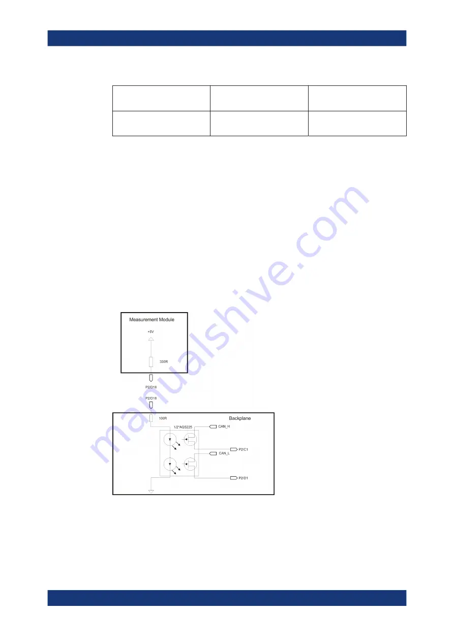
A 330-Ohm pull-up resistor between P2/D18 and +5 V on each module is responsible
for detecting a CAN module and activating the CAN bus. Normal cPCI or PXI modules
according to specification apply this pin to GND or leave it open. This ensures the CAN
bus is never in conflict with analogue voltages of the local bus.
Figure 3-10: Wiring CAN bus
External additional signals (AUX)
Two additional
external signals
(for example power supply voltages) can be fed into a
module via J20 on slots 5 through 16. The signals can be fed in the area of the CPCI
power pack by the CPCI power supply, an internal AC/DC module or another external
Construction