104
Rockwell Automation Publication 1715-UM001J-EN-P - December 2020
Chapter 2 Installation Instructions
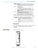
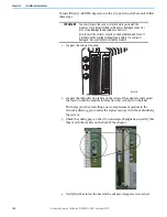
7. Push the adapter in until the dowel pin and connectors are fully mated.
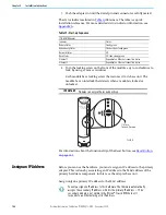
The status indicators listed in
illuminate. The table is a quick
installation reference. For more detailed status indicator information, see
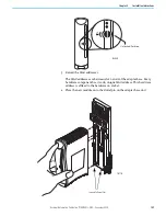
8. Turn the locking screw on the front of the module a 1/4 turn clockwise to
lock, by using a 9 mm screwdriver.
Each module has a locking screw that secures it to its base unit. The
module has an interlock that detects when a module is locked or
unlocked.
For information about the functionality of the Reset button, see
.
Assign an IP Address
Before you can use the hardware, you must assign an IP address to the primary
adapter. This is done by associating an IP address to the MAC address of the
primary hardware component, in this case, the adapter base unit.
Assign only one primary IP address to the MAC address.
Table 13 - Start-up Sequence
1715-AENTR Adapter
Indicator
Status
Module Status
Steady green
Redundancy Status
Flashes, then steady green
Network Status
Off
Rack Status
Off, then steady green
Ethernet 1
Dependent on Ethernet connection status
Ethernet 2
Dependent on Ethernet connection status
IMPORTANT
Modules run only in the locked position.
1/4 Turn
To Lock Postion
Rack Status
Ethernet 1
Ethernet 2
Module Status
Redundancy Status
Network Status
1715-AENTR
ADAPTER
Reset
32083 M
You only assign one IP address to this hardware. The firmware automatically
assigns the secondary IP address, which is the primary IP a 1. The
secondary module is not visible in the RSLinx® Classic RSWho tool. It
responds to an Ethernet ping of its IP address.

