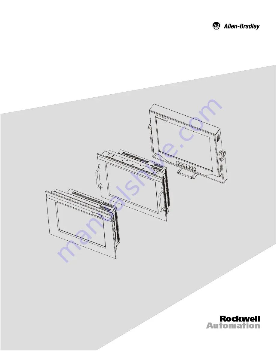
Industrial 18.1" Flat Panel Monitor
(Bulletin 6185-D, 6185-N, and 6185-V)
Installation and User Manual
Page 1: ...Industrial 18 1 Flat Panel Monitor Bulletin 6185 D 6185 N and 6185 V Installation and User Manual...
Page 2: ...ard wired electromechanical devices Because of this difference and because of the wide variety of uses for solid state equipment all persons responsible for applying this equipment must satisfy themse...
Page 3: ...Monitor Rockwell Automation offers the following models of the RAC6185 18 1 Flat Panel Monitor Panel mount 6185 D Rack mount 6185 N Versa mount 6185 V Figure 1 Models of the RAC6185 18 1 Flat Panel Mo...
Page 4: ...interface or power cords with Allen Bradley industrial monitors is prohibited Available Options The following options are available for the RAC6185 18 1 Industrial Flat Panel Monitor AC and DC power o...
Page 5: ...C Resistive Antiglare Touchscreen D Capacitive Antiglare Touchscreen W Antireflective Tempered Glass Screen Protector 4 Z Polycarbonate Screen Protector Power input A 85 to 265VAC Auto Switching 6 fo...
Page 6: ...Screen Protector 4 Z Polycarbonate Screen Protector Power input E 12 VDC 5 input F 120 240 VAC 6 ft USA Power Cord Remote or Attached 5 G 120 240 VAC No Power Cord Remote or Attached A 6 foot 1 8 met...
Page 7: ...ptional RS 232 serial extension cable Unpacking the Unit Before unpacking a new monitor inspect the shipping carton for damage If damage is visible immediately contact the shipper and request assistan...
Page 8: ...ight interfere with other equipment The Federal Communications Commission has prepared a pamphlet that addresses the problem of radio frequency interference to radio and television reception which sho...
Page 9: ...rds No slides or shelves are required because the panel mount 6185 D monitor is designed to be supported by the panel in which it is installed Figure 2 Generic Panel Mount Diagram Tools Needed In addi...
Page 10: ...installed in the panel Supporting panels should be at least 14 gauge to ensure proper sealing against water and dust and to provide proper support The mounting hardware supplied accommodates panels up...
Page 11: ...Industrial 18 1 Flat Panel Monitor 11 Publication 6185 UM001B EN P Figure 4 Panel Mount Dimensions Side View Figure 5 Panel Mount Dimensions Back View...
Page 12: ...monitor is not available following installation attach the power and video cables to the side of the monitor at this time Refer to the figure on Page 28 3 Install the monitor in the prepared cutout 4...
Page 13: ...N monitor is designed for installation in a rack cabinet that conforms to EIA standards for equipment with 19 483 mm wide panels Tools Needed You will need the following tools EIA panel mounting hardw...
Page 14: ...UM001B EN P Rack Mount Dimensions 6185 N This section shows the dimensions of the rack mount unit Use this information to ensure you have adequate space to install the unit and route cables Units are...
Page 15: ...Industrial 18 1 Flat Panel Monitor 15 Publication 6185 UM001B EN P Figure 8 Rack Mount Dimensions Side View Figure 9 Rack Mount Dimensions Back View...
Page 16: ...can be of two types Wide rails have holes spaced 0 5 12 7 mm and 1 25 31 8 mm on centers in a repeating pattern Wide rails are prevalent in Europe Universal rails have holes spaced 0 5 12 7 mm 0 625 3...
Page 17: ...ls Needed You will need a medium Phillips screwdriver for this procedure Versa Mount Mounting Guidelines 6185 V Observe the following precautions when installing this unit on an arm or in a yoke Ensur...
Page 18: ...M001B EN P Versa Mount Monitor Dimensions 6185 V The figures below show the dimensions of the Versa mount monitor without mounting hardware Units are in mm inches Figure 10 Versa Mount Monitor Dimensi...
Page 19: ...rial 18 1 Flat Panel Monitor 19 Publication 6185 UM001B EN P Figure 12 Versa Mount Monitor Dimensions With Power Supply Dimensions Figure 13 Versa Mount Monitor Dimensions Back VESA FPMPMI Mounting Lo...
Page 20: ...ns for mounting the Versa mount monitor Bench top mount arm mounts on horizontal surfaces using bolts or table edge clamp Wall mount arm mounts on vertical surfaces using bolts Bench or wall mount yok...
Page 21: ...Industrial 18 1 Flat Panel Monitor 21 Publication 6185 UM001B EN P Figure 15 Benchtop Mount Arm 6185 VxxxxxB Mounting Points Figure 16 Wall Mount Arm 6185 VxxxxxC Mounting Clearances...
Page 22: ...22 Industrial 18 1 Flat Panel Monitor Publication 6185 UM001B EN P Figure 17 Wall Mount Arm 6185 VxxxxxC Mounting Points Figure 18 Yoke Mounting Assembly 6185 VxxxxxD Mounting Clearances...
Page 23: ...Industrial 18 1 Flat Panel Monitor 23 Publication 6185 UM001B EN P Figure 19 Yoke Mounting Assembly 6185 VxxxxxD Mounting Points...
Page 24: ...rm or yoke 3 Mount the monitor on the arm or yoke To attach the AC to 12 VDC power supply to the Versa mount unit optional 1 Turn off the main switch or breaker 2 Remove three screws from the back of...
Page 25: ...r wall arm mount The Versa mount arm can be bolt mounted directly on a bench or a wall or you can mount it on a table using the edge clamp provided For detailed instructions on arm mounting or assembl...
Page 26: ...t The Versa mount unit can be mounted using a yoke bracket assembly that allows the operator to tilt or swivel the monitor for ideal viewing You can mount the yoke directly to the horizontal or vertic...
Page 27: ...Figure 22 Mounting the Monitor in the Yoke 2 Insert the other two knobs through the sides of the yoke and place the washers between the yoke and the monitor 3 Tighten each knob firmly by hand allowing...
Page 28: ...Monitor has connectors for attaching cables to the monitor The following figure shows the location of the connectors on the monitor Note Some connectors on your monitor may differ from these illustra...
Page 29: ...ion of components may impair suitability for Class I Div 2 ATTENTION EXPLOSION HAZARD Do not disconnect equipment unless power has been switched off or the area is known to be non hazardous Connecting...
Page 30: ...rly ground AC outlet is not always available and grounding using a 3 wire cord can easily be defeated If you fail to ground the monitor properly the setup may result in personal injury from electrical...
Page 31: ...le to the 12 VDC power input connector on the monitor See the figure on Page 28 3 Connect the IEC plug end of the AC power cord to the IEC AC power connector on the power supply Note If the power supp...
Page 32: ...ack mount 6185 N monitor 1 Turn off the main switch or breaker 2 Use the ground terminal on the monitor below the power connector to establish a chassis to earth ground connection Secure one end of a...
Page 33: ...ting Power to the Terminal Block 4 Restore DC power To connect DC power to the Versa mount 6185 V monitor 1 Turn off the main switch or breaker 2 Connect the power cable to the power supply if it is n...
Page 34: ...horizontal and vertical sync signals Please contact your Allen Bradley representative for more information To establish a signal using the HD 15 connector 1 Obtain a shielded properly terminated video...
Page 35: ...onitor Connecting the Optional Touchscreen Interface All Models An optional serial touchscreen interface connection to the host can be made through an RS 232 DE 9 female D shell connector located on t...
Page 36: ...the luminance controls and calibrating the video gain are provided for the 6185 D and 6185 N models Control Identification The figures below depict the location of the controls on the panel mount 6185...
Page 37: ...ow keys have two functions If the main menu is displayed pressing these keys moves the cursor to desired selection that needs adjusting If a control box is displayed may be used to adjust the value fo...
Page 38: ...ce the luminance of the monitor in low light conditions Luminance is different from brightness Luminance controls affect the amount of light passing through the display from the backlights Brightness...
Page 39: ...ived The monitor is not receiving a valid video signal On blinking slowly Off Backlight Off The monitor is still ON but the backlight is powered OFF Hold down both buttons for 2 seconds to disable the...
Page 40: ...t panel adjustment utility included with the monitor For instructions on starting the utility refer to Page 45 2 Press and hold down both luminance buttons for eight seconds Note The screen will go bl...
Page 41: ...o access Control Panel In Control Panel select Display to access monitor settings The options on the Control Panel screens may vary depending on your video driver Monitor Type If you are using Windows...
Page 42: ...bit color 1 5 Mb 1024x768 256 colors 8 bit 0 9 Mb High color 16 bit color 1 7 Mb True Color 24 bit color 2 4 Mb 1280x1024 256 colors 8 bit 1 5 Mb High color 16 bit color 2 6 Mb True Color 24 bit color...
Page 43: ...light and dark elements With a suitable image displayed on the screen adjust the contrast control to achieve the best balance between image brightness and fine detail rendition Position Information A...
Page 44: ...t Required You may also need to adjust the brightness or contrast of the screen image based on the physical location of the monitor Note The adjustment utility delivered with the RAC6185 18 1 Flat Pan...
Page 45: ...instructions are written with the rack mount and panel mount keys first and the Versa mount keys in parentheses For graphics displaying the location and operation of the controls on the monitor see Pa...
Page 46: ...es 640x480 resolution your video interface board is operating in 1280x1024 Interlaced mode You need to change the video board to Non Interlaced mode Consult the documentation for your video board for...
Page 47: ...e position options Note The vertical size is set automatically by the monitor to maintain proper video aspect ratio 1280x1024 resolution has a 5 4 ratio all others have 4 3 Step 4 Adjust the horizonta...
Page 48: ...twice to return to the on screen menu Step 7 Adjust the brightness To obtain the best display first set the brightness control to the appropriate setting under the lighting conditions in which the mo...
Page 49: ...The gray bars on the bottom of the screen image change to white 3 Adjust the contrast down until the white bar stays white and the first light gray bar changes back to light gray This is the optimal...
Page 50: ...ce Note For best results cleaning a monitor with the optional antireflective tempered glass display shield a solution of denatured alcohol is recommended to thoroughly clean the display Never use alco...
Page 51: ...llation instructions Replace suspected faulty cable s Fault in video source Test video source by connecting to another monitor that is known to be operational Fault in monitor Have monitor serviced Im...
Page 52: ...resolution Change the video source to 1280x1024 resolution Display is present but bars appear across it or roll through it Noise generated by other equipment in the environment is present at the video...
Page 53: ...Product technical training Warranty support Support service agreements Refer to the Rockwell Automation Allen Bradley Internet site at http www ab com for local contact information Technical Product A...
Page 54: ...2 cable with a male DE 9 D shell connector on the monitor end The cable provides a communications channel between the touchscreen controller which is mounted inside the monitor and an RS 232 C serial...
Page 55: ...8 1 Flat Panel Monitor provides a female DE 9 connector on the side panel This connector provides the serial interface for the touch controller Interconnecting wiring to the host serial port connectio...
Page 56: ...chscreen controller being used The RAC6185 18 1 Flat Panel Monitor uses the following controllers Resistive Elo TouchSystems model E271 2210 Capacitive MicroTouch model SMT 3 Once you have obtained th...
Page 57: ...oking into the pin end of the male connector or solder term end of the female connector Figure 33 HD 15 Video Connector The following table provides the pin numbers and corresponding pin assignments f...
Page 58: ...from the video source Figure 34 BNC Adapter Cable This table describes the signal types you can use with the connectors Table J BNC Signal Types BNC Signal Type Description R G B HS CS VS Sync on Gre...
Page 59: ...Supported Standards 720x400 at 70 Hz VGA text 640x480 at 60 Hz and 75 Hz 800x600 at 60 Hz and 75 Hz 1024x768 at 60 Hz and 75 Hz 1280x1024 at 60 Hz and 75 Hz native Video Input Signal RGB analog white...
Page 60: ...rating Shock 20g 1 2 sine 11 msec Non Operating Shock 30g 1 2 sine 11 msec Operating Vibration 0 015 in p p 5 53 Hz sine 2 0g peak 53 640 Hz sine Non Operating Vibration 0 015 in p p 5 53 Hz sine 2 0g...
Page 61: ...VGA text 640x480 at 60 Hz and 75 Hz 800x600 at 60 Hz and 75 Hz 1024x768 at 60 Hz and 75 Hz 1280x1024 at 60 Hz and 75 Hz native Video Bandwidth 135 MHz max video dot clock Video Input Signal RGB analo...
Page 62: ...Discharge 8 0K VDC IEC 801 2 level 3 Non Operating Electrostatic Discharge 20 0K VDC Operating Shock 10g 1 2 sine 11 msec Non Operating Shock 20g 1 2 sine 11 msec Operating Vibration 0 003 in p p 10...
Page 63: ......
Page 64: ...ional Business Machines Corporation VGA is a trademark of International Business Machines Corporation PC AT is a trademark of International Business Machines Corporation Microsoft is a registered trad...